• The move to the new server is done. There are some software and database maintenance updates in process. This has us passing the hat around to help out. We appreciate any donations. Seriously, even a dollar helps. The payment page may be found here - https://www.audiokarma.org/support.html

AU-X11 So it Begins

DB-7

Super Member
As many of you know I have collected several Sansui AU-X11.
All of them are JDM (Japan Domestic Market) 100v Integraded Power Amps.
All three are in good condition and work. Two of them work completely normal and sound great. The 3rd one has major glitchtness when using any of the volume controls but sound fine when you can settle it into a sweet spot.
Special thanks to @ARGOU For the inspiration to get such a beast, and more thanks to @ARGOU for the AU-X11 Service Manual.

I recently sent the first AU-X11 to get refurbished/restored.
With the permission of the Tech that is doing the work I would like to post progress as he does his work.

Disclaimer: I don't pretend to know much about electronics or amps and have very little knowledge about what the Tech is doing or why he is doing it. Any tips or advice that you may share will be passed on to the Tech

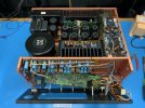
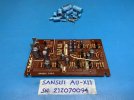
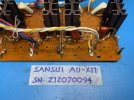
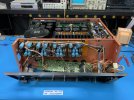
The Tech sent me these pics last night to signal the start of his fun.
IMG_7826..jpg
IMG_7827..jpg
IMG_7836..jpg
 
Last edited:
Register to hide this ad
Another technical note on the AU-X11's
Two of the later (newer) model ones have 4x10000uf and 4x6800uf main caps.
While the earlier one has 8x10000uf main caps.
Anyone have any idea of why Sansui would have changed this?
 
Last edited:
Another technical note on the AU-X11's
Two of the later (newer) model ones have 2x10000uf and 2x6800uf main caps.
While the earlier one has 8x10000uf main caps.
Anyone have any idea of why Sansui would have changed this?
Ofcourse I can not be sure. This started with the AU-D907F Extra as far as I can find and was continued in the alpha 907 models.
What I have read from Ishino lab is that Sansui was convinced that less etched foil electrolytic capacitors sound better. Reason could be that the ions in the electrolytic have less distance to travel and can provide charge faster. So a compromise between quantity and quality, one set of filter capacitors with more capacity, one set that is faster.
In the AU-D907F/G Extra this is more clear. Sansui went from 8x8600uF in the D907F to 4x12000uF + 4x4700uF in the Extra models. This two models were released at the time of the AU-X11. ( I would be curious if the later model X-11 also incorporated the MOSFETs as outputs for the SFF error correcting amplifier )
 
Any tips or advice that you may share will be passed on to the Tech
I would say the following is some findings that might your tech consider, I cant remember everything at ones but as much as I remember I will post.

Power amp boards :
R 43,44,58,59,57 ,41,39 are 500mw, in all 3 amps I have there are during signs on the PCB, it will be good to bump it up to 1W .
R29,30 the same , I bump it up to 500mw
(I have actually replace all the resistors with 500mw 1% 250/350v)
R12 should be 4.7K , check what you have. In one amp I have ,there was a factory instalment of a different value only to the one Channel.
C1 is getting too hot, I went with 105 degrees and if I had to do it again I would go with SMD at 125 degrees .

For MV-103,SV-3 the suggestion is 3x1N4150 close enough but the Green led
HLMP-C615-G0001 has identical forward voltage , sorry I have no picture but checking with peak atlas pro at my PC the two graph-lines are running one over the other, literally.
The 4.7uf electrolytic can be replace with PET and this is auditable enough;

R52 at PSU ,from the big capacitors to ground 10ohm 1/2W , I had one open and at the other amplifiers was way out of tolerance . I replace it with 1W.

As remember things I will post here.
Mind that this is suggestions , far from instructions , so I don’t get misunderstood.

In general the amp is the “kind” of equipment that what ever you choose to spend on , you will “hear” it .

FETs…. if I was you I will toss them out far before I consider replacing transistors.

Good luck, I’m so happy for you , soon you gonna have a unique experience in sound reproduction . The amp is kicking a@@s and taking names !
 
Last edited:
Thank you for all that info @ARGOU .
I am going to see my tech tomorrow and I will be sure to pass along that information.

The Tech is taking his time carefully choosing components. Being as how there are no tone controls on the AU-X1 and AU-X11 the right choice in components probably really matters with these factory pre-set amps.
 
Last edited:
Digging deeper into the AU-X11.
Words from the Tech
Looks like This unit has been already repaired long time ago by Sansui.. The repair is so clean and well done that only manufacturers will likely do such quality service and parts.

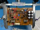
The Tech is now working on the power amp boards.
IMG_7915.jpgIMG_7891.jpg

This is why older audio should almost always be recapped at or before this age.
In these pics look closely at the bottom of the cap. Unseen disaster waiting to happen.

IMG_7895.jpg

Work in progress. Even though this board isn't finished yet, I wanted to show the progress so far. Waiting on parts.

IMG_7900.jpg
 
A new shipment of parts just came in so the tech is back working on the amp boards.
After some discussion we decided to upgrade the boards with Selected 1% metal film Vishay Low Noise resistors where he thinks nessessary.
Here is a pic of him starting the tedious job of replacing the resistors. Board is not done yet.

Before pic:

IMG_7891(1).jpg

After pic:

IMG_8060.jpg
 
One channel
R3, R9
R34, R37
R41, R42
R43, R44
R39, R40
R45, R46
R47, R48
R57, R58
R59
 

Attachments

  • Screenshot_20231103_194400_Acrobat for Samsung.jpg
    Screenshot_20231103_194400_Acrobat for Samsung.jpg
    64.9 KB · Views: 9
I use Panasonic ERG series, 1W, in the case of catastrophic failure it doesnt really matter if its 0.5W or 1W.
They were marked as fusibles in the SM's of Matsushita stuff
On datasheet they are specified as non-flammable only.

Every restorer has other point of view :)
 
Advice, opinions, and methods are always welcome.

Screensho(2).jpg
I looked over the actual Sansui AU-X11 Japan service manual several times before I talked to my tech.
Literally none of the resistor locations that were pointed out specify fuse resistors. Moot point I guess

The locations do call for flame proof resistors. The Vishay resistors are flame retardant. We know flame retardant, and flame proof are not quite the same thing but are a high grade substitute for our goal.

IMG_8077..jpg

We were looking for "flame proof" but cant find it together with "1% precision plus low noise"
We are after of one thing which is squeezing the last ounce of performance that is why were trying to upgrade and tweak.

We might not be looking hard enough but if they can direct us to that holy grail resistor, we don't have problems getting them.

This is my personal amp that I have asked the Tech to go beyond a normal restoration and to do what his experience and knowlege tell him to get the best sound quality possible out of it.

That means taking the teddy bear and safety blanket away.
 
The comments posted by @Bumpalump about the use of flameproof resistors caused my Tech to take a step back and do a hardcore search on the exsistance of a 1% low noise flameproof resistors.
After searching he found what he was looking for

He deemed it necessary to replace only the resistors that specify flameproof in the service manual, as the resistors he installed before are already a high grade flame retardant resistor. He still didn't agree with the use of fuse resistors.
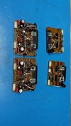
Here are the boards now completed.

IMG_8222.jpg

He has been working on the phono boards. They have had some work done to them already. He is tweeking them more. Here are the boards incomplete.

IMG_6612.jpg

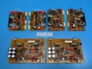
Here is a pic of the amp and phono boards together. Phono boards are still waiting on parts.
IMG_8224.jpg
 
More progress being made.
IMG_8323.jpg
IMG_8327.jpg
Power supply boards were corroded very bad by the glue. Some resistor legs were eaten completely away.

IMG_8313.jpg
IMG_6667.jpg
After cleaning some connections were completey gone and need to be repaired.
IMG_8332..jpg
Also changing the Series pass transistors

IMG_6666.jpg
 
I love the way you are documenting this - with labelled, good quality pictures. :thumbsup::thumbsup:
Thanks Hyperion.

The Tech sends me the pictures with limited information. I'm not sure if it's a case of him being a tad secretive, or because it would take up too much of his time to fully explain what he has done or is doing.

The issues with glue corrosion can never be stated enough.
This AU-X11 was a very good working Amp that you would never suspect those corrosion issues were lurking and waiting for the worst possible moment to fail.
 
The Tech sends me the pictures with limited information.
Nice work !!! Great pictures , in my coming restoration I think I will focus only to take good pictures and less words .

Can your tech tell you what transistors he chose for the F-3463 ?
 
Back
Top Bottom