• The move to the new server is done. There are some software and database maintenance updates in process. This has us passing the hat around to help out. We appreciate any donations. Seriously, even a dollar helps. The payment page may be found here - https://www.audiokarma.org/support.html

Audio Muting Circuit Question

dtone

New Member
Hello - New guy here. Great site with great info, so figured I'd seek some assistance. I'm not an electronics tech/expert, but have basic knowledge/skills/tools and ability to learn.

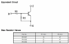
I have a 1990s era Roland GP-100 effects unit that stopped producing sound and think it might be related to the muting circuit which mutes when using the tuner function. The muting circuit had one bad/open transistor (Q47 - RN1309) with non-conducting B-E and B-C when measured removed from the main board. But, I'm not sure exactly how the muting circuit works, so I'm trying to understand it better (and if it's really the issue) while I'm waiting for the replacement transistor to arrive.

Can someone help walk me through the muting circuit to explain the basics of how it works (see section L17 on attached schematic)? Any assistance is appreciated.
 

Attachments

Register to hide this ad
Welcome to AK.
I'll give it a shot - the circuit appears to be controlled by a signal called "res" which I guess is reset. When res is 5 volts, Q 50 base is raised high enough so that it doesn't conduct. (assuming the small solid up arrow is 5 volts...) This will allow the voltage to base of Q46 to go down and shut the transistor off. This allows the voltage to the base of Q47 to go up, turning Q47 on and pulling the collector voltage low. That low voltage goes to q7,8,11,12,13,14,20,22 whichkeeps them from conducting, and there is output (not muted)
If the res line goes below 4 volts, Q50 will conduct, Q46 will conduct an Q47 will not conduct. Voltage at the collector of Q47 is allowed to go up, which causes q7,8,11,12,13,14,20,22 to conduct, muting the output. There are other resistors connected to the bases of Q13,14,20 and 22, so there are other routes to turn those transistors on and mute their outputs. on and mute different outputs.
Whew. my 2 cents
 
Great breakdown, sregor. Thank you. That's a big help and fills in the knowledge gaps I had. Sounds like the bad Q47 is the issue, unless there are others yet to be discovered.

Thanks for the welcome avionic. Yeh, seems to be a lot going on in that circuit.
 
Last edited:
I removed it from the board and used a DMM in diode mode. What would you suggest?
OK, didn't know if you had a transistor or semiconductor tester. Using only a DMM diode test the internal resistors will make them test bad when they're not.
 
Update: Replaced Q47. Also replaced Q50 (had some minor corrosion). Still no sound.

Guess I’ll start a separate troubleshooting thread.
 
Guess I’ll start a separate troubleshooting thread.
It's actually (IMO) better if you just keep it here. Less confusing for anyone following.
Start with the res signal, and voltages on the 3 transistors in the muting circuit. It looks like the res starts at IC12 just above the muting transistors in the schematic. Not familiar with it, but am guessing it is a turn on delay for the res signal, which also goes to some of the ICs on the schematic. Good luck. upload_2022-3-7_21-58-45.jpeg
 
It's actually (IMO) better if you just keep it here. Less confusing for anyone following.View attachment 2506211

Sorry for any confusion. For better or worse, I'd already started a thread w/some addt'l info (link here) and reference to this muting circuit thread.

Start with the res signal, and voltages on the 3 transistors in the muting circuit. It looks like the res starts at IC12 just above the muting transistors in the schematic. Not familiar with it, but am guessing it is a turn on delay for the res signal, which also goes to some of the ICs on the schematic. Good luck. View attachment 2506211

Thanks. I'll copy your suggestion and my initial response to the other thread.
 
Back
Top Bottom