• The move to the new server is done. There are some software and database maintenance updates in process. This has us passing the hat around to help out. We appreciate any donations. Seriously, even a dollar helps. The payment page may be found here - https://www.audiokarma.org/support.html

Audio Research D76

tubelectron

Super Member
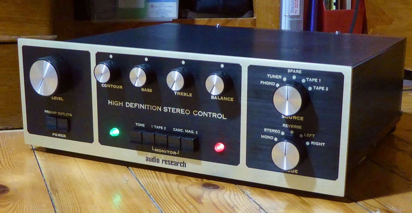
My Audio Research SP3A1...

V2HtOb-P1150925.jpg


... Will be happy to have a matching companion of the same era and excellent condition : an Audio Research D76. Pictures from the seller :

oyGuOb-ARC-D76-dlksells.jpg


The delivery is expected for the end of August to come, so Wait and See !

This D76 - like my SP3A1 - seems to have been well treated and preserved over the years, but in advance : what are the usual and peculiar quirks and failures - let's say idiosyncrasies - encountered on the Audio Research D76 ? ( @arts, maybe ? )

Cheers,

T
 
Register to hide this ad
Fan for sure. Looks like all the can caps have been replaced already, that’s good. The terminal strips look a little beat up, Digikey has the exact same ones for sale. Part GFTAX-4.
I like replacing the carbon comps and the zeners. You should also put 10 ohm resistors across the bias jacks if this hasn’t been done yet.
 
Fan for sure. Looks like all the can caps have been replaced already, that’s good. The terminal strips look a little beat up, Digikey has the exact same ones for sale. Part GFTAX-4.
I like replacing the carbon comps and the zeners. You should also put 10 ohm resistors across the bias jacks if this hasn’t been done yet.
There is no need to add 10 ohm resistors as they will mix up the NFB done in the cathodes. D76
has a bias test outlet for each tube that works very well
 
My bad! Meant 1 ohm, not 10 ohm.

The solder pads and traces can come off the board very easily. You have to be very careful removing components.
 
Is it just me or do these slightly-clear white PCBs used in a lot of low-volume 70s gear have the worst reliability? I also worked on a Mark Levinson unit that used similar-looking PCBs and the traces were very weak. In contrast, I've done dozens of Japanese 70s receivers and never had a trace lift on those using the exact same techniques and equipment.
 
Thank you Guys for your pertinent answers... :)


I would not add 10 ohms, but only 1 ohm/1W/1% in // with each 6550 control jacks.
Doing this would not change FB as much as 10 ohms, and allow a direct read of the tube current in DCmV (1mV=1mA).
But since these are shorting jacks, by the way this resistor would have no influence on FB during normal opaeration of the amp.

T
The bias test connectors connects a mA meter and breaks the cathode in the process, Any added
resistor is superflous.
The connector is a "telejack" ( a stereo connector of the same formfactor as a guitar connects with. I do not
know the us name) I glued one of these with a wooden pin so i could connect without burning my fingers.
This is connected to a mA meter. When the connector is inserted it breaks the cathode connection
and current flows through the meter.
This is not the same as measuring a voltage across a resistor, it's current metering,
 
Oh, OK : the matching model for my SP3A1 is the D76, not the D76A, since both are from 1974.
Yes, the serial number for the preamp does indicate 1974 but it had a trip back to ARC after the SP-3A-1 came out and was updated. Seems the D76 should get the A treatment at ARC to be the equivalent. But seems you are talking about the 76 being better with heat than the 76A.

I guess someone that bought the units in 74 might have sent the preamp in for service and just ordered a new set of tubes for the power and and having the -1 upgrade is the best of the upgrades. I don't know if ARC offered a D76 to D76A upgrade back then but the intro paperwork for the D76A indicated it would offer the mod. Would have been expensive with different boards and a lot more capacitors and such.

Gonna to be a very nice set of gear all fully working and cleaned up.
 
Is it just me or do these slightly-clear white PCBs used in a lot of low-volume 70s gear have the worst reliability?

not sure if these or the 1950s and early 60s ones are the worst, but both are fairly poor in terms of robustness IMO.
 
I've run into those type of boards in a few pieces of equipment. One amp was made in the mid 70's. The soldered eyes and traces do lift easily with those type boards. With either the 76 or 76A I think I would add a fan.
 
Don't know never had one of their amps so I don't know the serial number info. I would expect them to do something similar to be able to keep track of them, though.
 
All of the cans have been replaced; I would verify the values and voltages just to be sure, also the rectifiers, zeners and other components hidden on the Power Supply Board. This will also give you a chance to assess the quality of the workmanship. Check all of the carbon composition resistors for value/tolerance as well, they're usually pretty bad in the old ARC amps. R93 (15K/12W) is usually bien toasté;) I always up the wattage on this hard working item.

Edit: I probably posted this earlier. This is my own rebuild of my D76A

https://audiokarma.org/forums/index.php?threads/audio-research-score.675148/
 
There are a lot of differences between the D76 & D76A models, the majority of which occur in the power supply (not only in the HV sections but the heater supplies as well) and in the circuitry prior to the cross couplers.

Power supply: each is very different from the other, and each has some advantages over the other. No clear "better" here, but a slight edge to the A in the HV section, and to the non-A in the heater supply section. The A power supply upgrades could have easily been incorporated into the original non-a layout, but apparently there was a lack of engineering oversight.

Layout: clear advantage to the non-A in heat management and ease of servicing. Mine now sports a heat baffle between the rear of the vertical PCB and the five 6550's. Considering the amount of heat radiating out of those power tubes at high output levels, this is more of a "blast deflector" than a baffle:cool:

Inverting: rather than puzzle this out from the actual schematics (unless you have much free time, better eyes than me at this point, and don't mind the resulting headache,lol) you can find this info on the Simplified Schematics contained in the manual. They played a trick, but I'll give you a hint: initial reference point.
 
This is an an utterly unreasonable expectation for a vacuum tube amplifier; A 16kHz squarewave would require an output transformer with a bandwidth out to 160kHz. I would love to meet the transformer that could do that at 75 Watts;)
 
Yes, I would consider a 2kHz square a little more reasonable at those levels, but it would still be pushing things. At low levels, 10kHz should be not "too" bad.

Also, keep in mind the measuring capabilities of your instruments at these frequencies and with these waveforms, as most meters really start to fall off early and give erroneous readings.

You might be better off using the Siglent (that a 3055?) meter for measuring the output voltage of the amplifier, as it has far better frequency extension and Crest factor than the Fluke. When you start getting into the distortion products, you're gonna need all the help you can get.
IIRC, my 3055 is +/- 3% between 50kHz and 100kHz.

Probably a bit late to ask now, but you are being very careful keeping the grounds between the input and output isolated?

Edit: Sorry, just saw the scope isolation rig in the photo. Past my bedtime,lol
 
Last edited:
"arts, post: 15823439, member: 200015"

Yes, I would consider a 2kHz square a little more reasonable at those levels, but it would still be pushing things. At low levels, 10kHz should be not "too" bad.

---> Yes ! But look at the 400Hz SQwave : the "springy" overshoot are quite important IMHO. This is probably due to the total amount of FB the D76 has.

Also, keep in mind the measuring capabilities of your instruments at these frequencies and with these waveforms, as most meters really start to fall off early and give erroneous readings.

---> My Flukes 87 are 20KHz bandwith TRMS, I should have taken my 287 which offers 100KHz, but it's not that important, as the Siglent scope reads also the voltage. Moreover, the handheld Flukes are independent from GND, which is not the case for the Siglent 3045X (I thought it would have a GND lift switch, but no).

You might be better off using the Siglent (that a 3055?) meter for measuring the output voltage of the amplifier, as it has far better frequency extension and Crest factor than the Fluke. When you start getting into the distortion products, you're gonna need all the help you can get.
IIRC, my 3055 is +/- 3% between 50kHz and 100kHz.


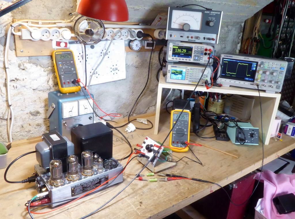
---> the Siglent 3045X is placed at the input of the amp, where it is more important to check the voltage stability vs. frequency IMHO. My old Leader LAG-26 audi generator proves to be nearly as reliable as my Siglent SDG805-10 function generator in amplitude... :cool:

Probably a bit late to ask now, but you are being very careful keeping the grounds between the input and output isolated?

---> Yes, otherwise the measurement is not possible, due to the 4R grounding of the D76 speaker output.

Edit: Sorry, just saw the scope isolation rig in the photo. Past my bedtime,lol

---> well, it's not a premium solution, but it works... The next time, I will use a separation transformer for the oscilloscope - at least.

This morning, as I was unsure, I re-did the 75WRMS test, checking both channels : absolutely no difference between them, so the behavior of the amp could be considered as normal.

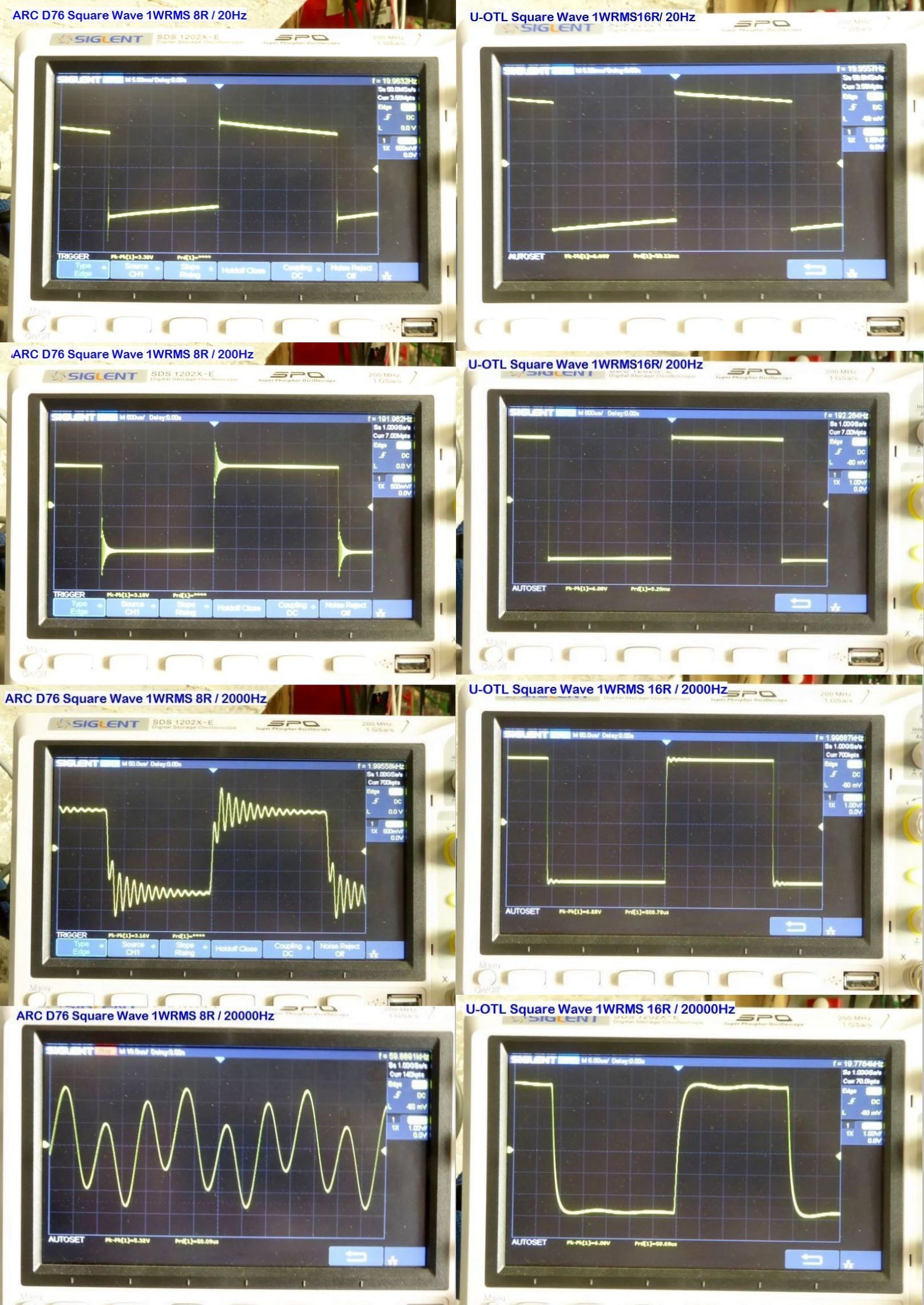
Then I made test at 1WRMS at 20/200/2000/20000Hz on my U-OTL, for a comparison with my D76 :

0RLzOb-P1160174.jpg


0RLzOb-D76-Left-vs-U-OTL-Right-1W-SQ-21-08-2022.jpg


The absence of the output transformer is... How can I say it ?... Noticeable ! :D;)

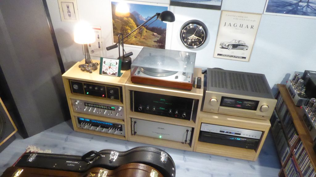
The D76 took his place in the rack, but I will indeed add a back ventilation to extract excess heat, which will be powered in the same time as the amp by the preamp "switched AC conveniences outlets".

zWLzOb-P1160177.jpg


Cheers,

T
You certainly need a fan or two. Also make sure that air can come through the amp, you really should need ventilation
holes in the front. Open holes below and fans sucking out at the back might be a solution.
 
I think I’d swap the Accuphase and ARC if possible. You really want the ARC to be ventilated properly because it will get extremely hot in that tight space.
 
Agreed that 16 kHz square wave at rated power is not only an unreasonable test, but yields virtually no useful information as a result. I would be more interested in how much un-distorted sinusoidal power output can be developed at 20 Hz. If I recall correctly, ARC was only specing full rated power output down to 30 Hz in their earlier models, but I don't know -- my memory could be foggy. It would also be interesting to see how well the amplifier handles a cap only load across the output -- say just a 0.22 uF cap across the full secondary, while displaying a 10 kHz square wave at 1 watt. That value is certainly more capacitance than the amplifier would ever normally see otherwise unloaded in use, but it gives a clear indication of how the amplifier can handle such abnormal loading conditions, which is important. In my D115 project, I had to make a slight adjustment to the response tapering caps at the input stage in one channel to achieve the best cap only load stability.

You can forego the need for any isolation hoops due to the 4Ω tap being grounded by using a 4Ω load instead of an 8Ω load. Connected between the 4Ω and 16Ω taps, it will properly load the amplifier, and if the 4Ω tap is treated as the ground connection, it will allow the input and output connections to maintain ground integrity while conducting your tests.

Beautiful looking amp!

Dave
 
Back
Top Bottom