

You are using an out of date browser. It may not display this or other websites correctly.
You should upgrade or use an alternative browser.
You should upgrade or use an alternative browser.
Audire Forte250 Build
- Thread starter hamrules
- Start date
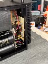

Here we go. Hooked up a couple DMM’s, DC offset & emitter resistor. Used 75watt bulb in DBT. Powered on bulb glowed hard and dimmed down to almost nothing. All right! Plugged directly into variac and turned on. After about 10 minutes emitter voltage was 5mv and DC offset was at 24mv. So far so good. I was hoping to see a lower number for DCO though. I spent a lot of time matching those transistors for not the benefit I thought I’d see, I really thought it would be under 10mv. What else could be affecting the DCO?
Last edited:

Back from the holiday weekend.
First, congrats on the beautiful work you've done and the amp firing up without magic smoke.
Yes, 24mV is quite high and not an encouraging starting point. Were the inputs shorted when you tested? What parameter(s) did you match for? What measurement(s) did you consider sufficiently matched?
It is difficult to get it down below several mV because there are no offset trimmers, but for this pretty straightforward circuit and fairly limited components it generally comes down to the diff pair and/or the parts immediately surrounding them.
Exactly how did you match the input transistors? If you measured them after the exact same settling time (sufficient to limit further significant drift), protected them from air currents, and ran them at the same current, try to recall if there was any variation in testing conditions, including handling time and heat transfer from your fingers to the parts. I've made several different jigs for measuring BJTs and JFETs that control for voltage, current, external temperature, air currents and time. I only use my Peak DCA75 for initial bins of ranges, then my BJT jig for nulling tail currents between pairs. It's very time-consuming and it will take easily an hour and a half to test 20-30 transistors just to get a few tight matches.
Because you are using non-standard parts, there is also some potential that the current sources are not set optimally for the different supply to each diff pair.
Did you replace the current source transistors? If so, did you do a rough match of those parts? If not, did you test them for hFE? Did you check the resistance of the current source emitter resistors? I haven't seen a large percentage of the metal film resistors in these amps drift off value, but it happens. Did you check the values of the 36pF caps coupling to the VAS? Did you check the values of the NFB components? I have found the film caps in these positions in some amps that have drifted. Did you verify the 82R5 values of the base resistors to each diff pair transistor? Check each 1N4148?
Basically, start at the diff pair with 100% confidence, then measure everything radiating from those parts in the input circuit. This is a very simple, streamlined circuit, so small variations are amplified through the circuit path.
Don't get discouraged. You'll get it right and it will sound awesome.
I hate to remember what I went through with the first early Crescendo I repaired, having never worked on a CFP design before. Similar input stage but the output stage tripped me up until I looked at similar schematics from other makers.
First, congrats on the beautiful work you've done and the amp firing up without magic smoke.
Yes, 24mV is quite high and not an encouraging starting point. Were the inputs shorted when you tested? What parameter(s) did you match for? What measurement(s) did you consider sufficiently matched?
It is difficult to get it down below several mV because there are no offset trimmers, but for this pretty straightforward circuit and fairly limited components it generally comes down to the diff pair and/or the parts immediately surrounding them.
Exactly how did you match the input transistors? If you measured them after the exact same settling time (sufficient to limit further significant drift), protected them from air currents, and ran them at the same current, try to recall if there was any variation in testing conditions, including handling time and heat transfer from your fingers to the parts. I've made several different jigs for measuring BJTs and JFETs that control for voltage, current, external temperature, air currents and time. I only use my Peak DCA75 for initial bins of ranges, then my BJT jig for nulling tail currents between pairs. It's very time-consuming and it will take easily an hour and a half to test 20-30 transistors just to get a few tight matches.
Because you are using non-standard parts, there is also some potential that the current sources are not set optimally for the different supply to each diff pair.
Did you replace the current source transistors? If so, did you do a rough match of those parts? If not, did you test them for hFE? Did you check the resistance of the current source emitter resistors? I haven't seen a large percentage of the metal film resistors in these amps drift off value, but it happens. Did you check the values of the 36pF caps coupling to the VAS? Did you check the values of the NFB components? I have found the film caps in these positions in some amps that have drifted. Did you verify the 82R5 values of the base resistors to each diff pair transistor? Check each 1N4148?
Basically, start at the diff pair with 100% confidence, then measure everything radiating from those parts in the input circuit. This is a very simple, streamlined circuit, so small variations are amplified through the circuit path.
Don't get discouraged. You'll get it right and it will sound awesome.
I hate to remember what I went through with the first early Crescendo I repaired, having never worked on a CFP design before. Similar input stage but the output stage tripped me up until I looked at similar schematics from other makers.
Oh, inputs shorted - no. Oops.
I used the DCA75. I matched them for VBE & HFE. VBE they were all the same, HFE within 2 (not +/- just 2). I test them in the tape they send them in so I’m not holding them.
The rest of your questions, no I didn’t test any other parts.
I used the DCA75. I matched them for VBE & HFE. VBE they were all the same, HFE within 2 (not +/- just 2). I test them in the tape they send them in so I’m not holding them.
The rest of your questions, no I didn’t test any other parts.
Excellent, John.
Though you've already got your input differential transistors worked out, I thought I'd add to the thread to show a variation on how I bond quads like this.
My earlier post shows the thin copper heat spreader glued to the top, but when I've got diff pairs in other amps that are mounted close to each other, but the complementary parts are too far to connect with a heat spreader, I use heat sink paste between the transistors, push them close together, then use copper tape to wrap the diff pairs, followed by heat shrink over the copper-tape-wrapped pairs. That does a good job of keeping the individual pairs tracking together, but doesn't really keep the complementary transistors tracking with each other. I think the coper wrap does a better job than a heat-spreader glued on top of the transistors, since the front and back, as well as sides, have a lot of surface area.
My other approach is just to use thermal epoxy to join and encase individual pairs, which encapsulates them together and works really well.
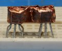
With this quad, I used thermal glue between the tightly-fitted transistors, then cut a rectangular shape of copper sheet, formed it over the quad, then wrapped around the bodies with 1/4" copper tape. The resulting copper encasement takes advantage of the surface area of the circumference of the parts, and also joins them at the top. A drop of polyurethane glue keeps the wrap from ever coming loose and shorting anything.
I've played with a lot of different potential substitutes for the MPQ6600 diff quad packages, as alternatives to the MPS8099/8599, just for the sake of experimentation. The latter are 80V parts so more than sufficient for most Audire amps, but those like yours with higher rail voltages that used the MPQ7501 would benefit from something in the 100V range, so I've bought 100 each of ZTX453/553 which are reported to be very low noise transistors to match up. These have a Vceo of 100V and a Vcbo of 120V, more than enough for the rail voltages in the Forte 250, and I expect, other Audire amps I have yet to work on.
As an example, I bought 50 each (most expensive of all), matched up several, then put together this quad of ZTX851/951, which are renowned for a very low noise figure. Most, but not all of their other specifications are close to the MPQ6600 and the MPS replacements and they have a Vceo of 60V and Vcbo of 150V. These will go into my Crescendo for testing.
I also bought 100 each of ZTX853/953 to match up. A rather expensive experiment, as the cost was about $1 each. I usually buy at least 100 of each transistor I need for differential pairs so I get really tight matches, but these were all over the place with hFE, and even those that matched that parameter had poorly matched collector currents between pairs on my matching jig. As a result, there are really not that many tight matches (by my standards) with these types of transistors. Additionally, the ZTX453 are much higher hFE than the 553, more than the other part numbers.

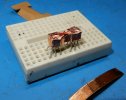
Though you've already got your input differential transistors worked out, I thought I'd add to the thread to show a variation on how I bond quads like this.
My earlier post shows the thin copper heat spreader glued to the top, but when I've got diff pairs in other amps that are mounted close to each other, but the complementary parts are too far to connect with a heat spreader, I use heat sink paste between the transistors, push them close together, then use copper tape to wrap the diff pairs, followed by heat shrink over the copper-tape-wrapped pairs. That does a good job of keeping the individual pairs tracking together, but doesn't really keep the complementary transistors tracking with each other. I think the coper wrap does a better job than a heat-spreader glued on top of the transistors, since the front and back, as well as sides, have a lot of surface area.
My other approach is just to use thermal epoxy to join and encase individual pairs, which encapsulates them together and works really well.
With this quad, I used thermal glue between the tightly-fitted transistors, then cut a rectangular shape of copper sheet, formed it over the quad, then wrapped around the bodies with 1/4" copper tape. The resulting copper encasement takes advantage of the surface area of the circumference of the parts, and also joins them at the top. A drop of polyurethane glue keeps the wrap from ever coming loose and shorting anything.
I've played with a lot of different potential substitutes for the MPQ6600 diff quad packages, as alternatives to the MPS8099/8599, just for the sake of experimentation. The latter are 80V parts so more than sufficient for most Audire amps, but those like yours with higher rail voltages that used the MPQ7501 would benefit from something in the 100V range, so I've bought 100 each of ZTX453/553 which are reported to be very low noise transistors to match up. These have a Vceo of 100V and a Vcbo of 120V, more than enough for the rail voltages in the Forte 250, and I expect, other Audire amps I have yet to work on.
As an example, I bought 50 each (most expensive of all), matched up several, then put together this quad of ZTX851/951, which are renowned for a very low noise figure. Most, but not all of their other specifications are close to the MPQ6600 and the MPS replacements and they have a Vceo of 60V and Vcbo of 150V. These will go into my Crescendo for testing.
I also bought 100 each of ZTX853/953 to match up. A rather expensive experiment, as the cost was about $1 each. I usually buy at least 100 of each transistor I need for differential pairs so I get really tight matches, but these were all over the place with hFE, and even those that matched that parameter had poorly matched collector currents between pairs on my matching jig. As a result, there are really not that many tight matches (by my standards) with these types of transistors. Additionally, the ZTX453 are much higher hFE than the 553, more than the other part numbers.

Have the left board done finally.
Fired it up after DBT showed good to go.
Under full power bias went to 15.5mv, turned that down to about 8.5 just to keep it safe for now.
First IC is a bust as DCO is 65mv. Have another 5 to try and see if I get lucky with two that are way lower. If not, back to the matching of transistors. My favorite pastime, ha ha.
Another issue in assembly. When I was putting the board back in it wouldn’t go down so the bias transistor would contact the heatsink. Well lo and behold the parts soldered right above the drive transistors that are mounted to the heatsink were sticking out to far. After some messing around I just barely got it. In hindsight the parts in those couple areas would be better off by bending the leads over and soldering to keep it way low.
Nice job, John.
Did you short the inputs?
Do you have the boards fully assembled onto the heat sink assembly so you can push it into position onto the side of the chassis? Do the same with the other one, and put the lid on, then check bias in cycles. As you know, bias will change as the entire assembly heats up.
Please show the entire assembled heat sink.
The DCO may also change, so every few minutes check DCO - the diff quad package may need to get up to nominal operating temp. That will of course change as the unit heats up in full operation.
True matching is not easy to accomplish without really good, consistent temperature control and a proper jig. The Peak is good for sorting for hFE, but a one or two point difference in hFE can show up as a 3-5% or more mismatch in collector current. Those MPQ packages are old, and have probably aged just sitting on the shelf - they certainly do in use, as you've seen.
Yes, the parts fitment is really critical in these particular amps because of the very tight package of the L-bracket, heat sink, and board mounting. Absolutely my least favorite Audire amp package to work on.
I edited your image above so you can see how pretty it is!
Don't forget the folded aluminum heat sinks on the appropriate TO-92 transistors.
I've found these amps to have very stable bias, so if you see anything different, make sure your bias transistor is in good contact with the heat sink with paste between the part and heat sink.

Did you short the inputs?
Do you have the boards fully assembled onto the heat sink assembly so you can push it into position onto the side of the chassis? Do the same with the other one, and put the lid on, then check bias in cycles. As you know, bias will change as the entire assembly heats up.
Please show the entire assembled heat sink.
The DCO may also change, so every few minutes check DCO - the diff quad package may need to get up to nominal operating temp. That will of course change as the unit heats up in full operation.
True matching is not easy to accomplish without really good, consistent temperature control and a proper jig. The Peak is good for sorting for hFE, but a one or two point difference in hFE can show up as a 3-5% or more mismatch in collector current. Those MPQ packages are old, and have probably aged just sitting on the shelf - they certainly do in use, as you've seen.
Yes, the parts fitment is really critical in these particular amps because of the very tight package of the L-bracket, heat sink, and board mounting. Absolutely my least favorite Audire amp package to work on.
I edited your image above so you can see how pretty it is!
Don't forget the folded aluminum heat sinks on the appropriate TO-92 transistors.
I've found these amps to have very stable bias, so if you see anything different, make sure your bias transistor is in good contact with the heat sink with paste between the part and heat sink.
Yes shorted the input.
Yes the left side is fully assembled.
Yes the T092’s have the heatsink’s on.
I’ll try the rest of the IC’s since there here. If nothing good I’m thinking I’ll take the board back out and replace the parts where those heatsink-mounted drivers are to get that fit the best it can be. Then mess around with transistors again.
Yes the left side is fully assembled.
Yes the T092’s have the heatsink’s on.
I’ll try the rest of the IC’s since there here. If nothing good I’m thinking I’ll take the board back out and replace the parts where those heatsink-mounted drivers are to get that fit the best it can be. Then mess around with transistors again.