• The move to the new server is done. There are some software and database maintenance updates in process. This has us passing the hat around to help out. We appreciate any donations. Seriously, even a dollar helps. The payment page may be found here - https://www.audiokarma.org/support.html

Aux connection to Magnavox model 1RP623

chrisrennick

New Member
I have just signed up and have found a lot of great info here. I have a Magnavox console from my grandmother that has never left the living room and I'd like to hook up an external music source given the source selector knob has an Aux option.

Here are some pictures of the unit for context.
upload_2022-2-20_16-20-53.jpeg

upload_2022-2-20_16-21-59.jpeg

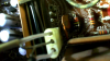
Based on other posts here I opened up the back and took some photos of where I think the aux connection needs to be made.
upload_2022-2-20_16-23-51.png

So that ch-1 set of 3 poles looks like it is a female connector at the top for possibly the left channel with a male pin for the common in the middle and another male pin for the right channel at the bottom.

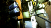
The plug attached to ch-2 goes to the turntable tone arm. The black wire goes to the lower pin, the white wire to the upper pin and the commons are twisted together and go to the center pin. Here is a picture with a ruler for size reference
upload_2022-2-20_16-32-17.png

So, what kind of connector is that exactly? Where do I buy such a thing? Also is it weird that the pins on CH-1 are 2 male and 1 female? Was this some sort of polarity fool proof technique to prevent Left/Right from being mixed up?

Any help is appreciated!
 
Register to hide this ad
It would be easier if you could pull the whole unit out of the cabinet. That's actually a "tape in" plug/input.

Personally, I am not sure that you can buy the plug but if it were me, I would hard wire (solder) some RCA jacks to those pins. Not sure of your area of expertise but I could easily do this.

If that is too much of a hassle for you, you can always buy or build a simple switch box and just use the phono jacks.

Channel 1 and 2 is the same as right and left and center is common ground.
 
Thanks for the quick reply! I'm a bit paranoid about pulling the board out of the cabinet, but doing a good soldering job would require doing so. What do think of trying some of the Molex style pins (2 Female and 1 Male) to see if they can establish a robust connection with the pins on the board? It would then be a simple matter to hook up a 3.5mm TRS female jack which would work directly with a lot of audio devices.
 
If it's the same, unless you are using the turntable on a regular basis, just unplug the turntable connection and plug it into the tape input.

I believe that the turntable has male RCA's that plug into the bottom of the turntable itself so you can just use those with 1/8 inch or TRS adapters. All the adapters you could ever need are available on the net especially at Amazon (no affiliation).

The phono in those consoles use ceramic cartridges so you can either leave the plug at the circuit board alone or plug it into the tape input. The phono and tape inputs are basically both line level so either would work.

Probably be best to use the tape input as the turntable probably needs to be switched on when using it in phono mode.
 
Last edited:
The turntable is working well. The needle could likely be replaced but my Santana "Abraxas" and Moody Blues "A Question of Balance" albums are so old that it's hard to tell if the needle or the record is scratchy. The RPM seems to be right on though.

Yeah, I saw the RCA plugs under the turntable connecting to the 3 pin plug on the board. So that could be nice place to insert a switched input via the phono selection... hmmm ... yes, the turntable needs to be "On" for amp to have power when in the phono position and the platter spins then.

I'll play with the TV/TAPE pins for now, cheers!
 
I don't suppose its actually got a set of input jacks already available on the back panel ?

If not, thats probably a 3 pin molex connector. Confirm the spacing and pin diameter but this is probably what you need. Looks like they may have done 2 female and one male pins on the plug, but that also shouldn't be a problem. Got this pic from ebay, if you search "3 pin molex connector" it will show up.

s-l1000.jpg
 
On the back there is only the antenna and the external speaker connections. The pins are 1/4" center to center and appear to be the .096" diam. pins i.e., bigger than 1/16" and less than 1/8". I pulled the phono jack out to get a more precise view but unfortunately one of the pins pulled from the board so now I've lost the left channel of the record player -- drat -- I'm so bummed! Now I will need to pull the chassis to re-solder that connector if I want to listen to more records.

Weirdly the TV/TAPE CH-1 is F M M on the board but Phono CH-2 is M F F on the board so the existing plug can't be moved from CH-2 to CH-1.
 
With the phono jack out I did another measurement. The pitch appears to be a hair more than 3/16" so that maybe makes it the 5.03mm pitch. The pins themselves are really close to 3/32" in diameter so that is basically the .093" size. A 2.13mm diam. computes to the .084" size which may be a tad too small. I wish I had my micrometer with me. Anyhoo, I've got some pins/connectors coming in the mail and will report back if I've decided right or wrong.
 
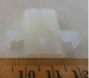
The molex connectors arrived and they fit perfectly. Here is a picture with ruler of the new connector
upload_2022-2-26_11-9-17.png

As you can see we have the 5.03 mm pitch. When I cut off the tabs it is the exact form factor of the existing phono plug.
Amazing how this standard has endured.

The .093" pins fit with the existing combination of male and female pins on the board. I "exercised" the female pins so that if I had to remove the connector to make adjustments (and I did!!) then the connection wouldn't be so tight that I'd pull more pins from the board. The wires to the female 3.5mm jack were only 26 gauge so I soldered them to the Molex connectors because the crimping tabs were not holding the wire in place. Once I had the solder nicely flowed into place and the wire secured, I closed the crimping tabs so I could insert the pins into the connector.

I hooked up my kindle fire and my cell phone and it works. I have to turn up the volume a bit from what is comfortable with the radio however. Thanks to all who helped me through this process!

The loudness dial seems a bit scratchy. Is that another one of those things that might require pulling the whole board to rectify properly? Maybe a new thread down the road when I feel up for that?
 
Output from most phones is on the feeble side, so not surprised you have to crank it a bit but good to know it works and you have a nice clean solution.


Control probably needs a squirt of cleaner, whether or not you need to pull the board depends on access to the back side of the control.
 
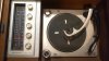
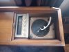
Sorry to high jack thread it's the only thing I've found online that matches my unit exactly I have a very good condition everything works as it should here's pictures
 
Sorry to highjack thread I have not been able to find any thing on this unit would like to know what it's worth everything works as it should it's model 1rp623 thank if there some place to post this please let me know thank you I'm in south bend indiana IMG_20230406_145725956.jpg IMG_20230406_145717045.jpg IMG_20230406_145711499.jpg IMG_20230406_145705949.jpg
 
Back
Top Bottom