• The move to the new server is done. There are some software and database maintenance updates in process. This has us passing the hat around to help out. We appreciate any donations. Seriously, even a dollar helps. The payment page may be found here - https://www.audiokarma.org/support.html

Avionic - Couple of Yamaha Questions

Vintage74

New Member
Hi,

Sorry to bug you just I had a few follow up Yamaha questions after digging into my CA-610 II and cleaning the pots and switches.

1. Any advice on removing the balance knob?

I completely removed both of the set screws from behind the sub-panel and no matter how hard I pull on the knob it's not budging. Seems like it's putting a lot of stress on the volume / balance pots when I pull on it.

I read a few other AK posts about that knob suggesting the "2 spoons" method but I just wanted to make sure I wasn't missing something else holding it on.

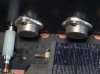
2. I notice a white crust around the output transistors (see attach pic). Is that corrosion and is that normal or a sign of an issue?

If it is normal is there anyway to safely clean that? (my goal being to clean this thing inside and out to a factory fresh look)

3. I checked the DC voltage across each of the output transistors and I got:

transistor 1: 47.3
transistor 2: -14.19
transistor 3: .311
transistor 4: -14.16

So two with a negative value, one very low and the other in the range you had suggested. Does that look correct to you?

The unit has been unplugged for a few days.

Any advice would be much appreciated!

Mark
0-1.jpg
 
Register to hide this ad
3. I checked the DC voltage across each of the output transistors and I got:

transistor 1: 47.3
transistor 2: -14.19
transistor 3: .311
transistor 4: -14.16

So two with a negative value, one very low and the other in the range you had suggested. Does that look correct to you?
Is this with the power switch off?

You have three threads going for the same unit , same issues.. It is counter productive..
 
I completely removed both of the set screws from behind the sub-panel and no matter how hard I pull on the knob it's not budging.
Keep turning the knob clockwise ..While pulling. The balance shaft probably has burr's from the setscrews being over tightened.
 
Hi,

Ahh... Sorry about the multiple threads... I'll keep all my questions in this one from now on.

The clockwise twist while pulling worked. It came off super easy!

Now I ran into a new issue.

How do I remove (and then put back on) the VU meters? I didn't realize they are attached to the faceplate.

Those voltage readings are with the power switch off (and unplugged for a few days).

I'll take a pics of the filter capacitors tomorrow and post it (are those the two large black capacitors I posted in a past thread?

Mark
 
How do I remove (and then put back on) the VU meters?
Leave the meters fastened to the face plate. Unsolder the meter wires at the wire wrapped pins on the circuit board. Don't try to unsolder the wires from the meters.
 
I'll take a pics of the filter capacitors tomorrow and post it (are those the two large black capacitors I posted in a past thread?
Don't bother.. I was thinking those were " power on " voltages at first. Until I went back and re-read the other two threads.
 
Hi,

I'll so that on the VU meters...

So on the output transistors it will be safe to clean (tough) them even the one with the 47v reading?

Mark
 
transistor 3: .311
When probing the transistors you may have to scratch through oxidation on the transistors case.To get a good electrical contact. This should be the same voltage as transistor # 1 ( 47v)
 
Hi,

I took readings on the output transistors again this time scratching down a little spot on the metal case as well as probing the screw threads that feed all the way through the output transistors on the other side of the heat sink and got:

Transistor 1: 30
Transistor 2: -13
Transistor 3: .282
Transistor 4: -13

So #1 is down from a few days ago (now it's been unplugged for over a week) and all the others still have the same readings.

Is #3 not matching the reading of #1 an indication of a issue?
 
Is #3 not matching the reading of #1 an indication of a issue?
Maybe.Both of the NPN transistors get there power from the same place.The + side of the two main caps. The PNP transistors get there power from the - side of the two main caps. Thats why #2 ans #4 are the same.May have a broken or cracked solder connection for that transistor socket.Or a cracked circuit board trace.
 
Ahhh... That doesn't sound good...

Would there be some other "symptom" I could use to diagnose if that is causing an issue?

How do I go about finding a broken or cracked solder connection for that transistor socket or a cracked circuit board trace?

Would it be something I can visual see on the bottom side of the circuit board?
 
Would it be something I can visual see on the bottom side of the circuit board?
Yes.. Do a visual of the transistor sockets solder connections.Bright light and magnification. Look for circular cracks in the solder around the socket leads.
 
I would definitely check where the legs from the output transistor sockets go through the board. When I fixed and recapped mine a few years ago there was noticeable circular cracking in those solder joints. Not totally broken but working its way there.

You might want to check the voltage at the metal pads on the front side of the heat sink the output transistor mounting screws go through. As much thermal paste as there is on the edge of those transistors if someone remounted them they could have done what I did when I remounted mine the first time. I got a bit too much thermal paste on the mounting screw threads and it isolated one output transistor from the power supply. Blew a replacement driver transistor or two until I figured it out. I had to clean the screws, mounting holes, and all metal screw mating surfaces. Being more careful the second time I put it back together.

The CA-610II was my first fix and repair project. Now I always check the voltage at the cases after mounting those types of output transistors. Driver transistors trying to do the job at normal listening levels tend to only last a few minutes before they die.

IMG_20180521_020914.jpg
 
Back
Top Bottom