• Please note that Audiokarma will be offline briefly for updates early on Monday morning, September 28th.

B-2101 - 4619 Power Amp boards

JSMATT

Member
Purchased a used B-2101 - did not test it live.

Have recapped and replaced some resistors that had glue for all boards.

First step was to complete the 4618s and set their trimmers, once those two boards etc. were redone. Waited to do the 4619s until the unit worked off DBT which it did. Then I pursued the 4619s with new caps and other updates like thermal paste redo.

Put the unit back together and put it on DBT. Bright light. WTH.

Part of my work on this was redoing all the white thermal paste. That included the double diode sets resting between the power caps.

I undid the big caps - had done that once and thought I bricked them - hence my earlier post on tricks/tips to undo the big caps associated with them. Even with the caps undone, the bulb burned brightly. WTH.

So, I pulled that small board and its tall heat sinks out. And I looked. And looked again. And, finally, saw that a splash of solder had bridged two traces. &$%#!

Reassembled everything again, carefully, and put it on the DBT - bright them dim and that great sound of relays closing. Finally, sorted... or not.

Next steps were to set all the bias etc. to spec. Turned the 2101 on, confirmed vol. pots min and let it sit.

I started with the right channel. All the steps required went smoothly, not withstanding the 4618 'wandering bias' issue that has received attention again on Magnus Black's post. I had set the new trimmers to what the originals were and that certainly saved a lot of fiddling.

On to the left channel. I could set the kVR1 0n 4618 and get it to 0 mV. On may way I thought, tunes in an hour!

I went to set the KVR4 and KVR3 on 4619 - that was a train wreck. Every time I got them set to 6.6 mv, the transistors seemed one step from meltdown, as the heat sink was too hot to touch. Something was very much wrong on this left channel. Right channel Output Hot and Emitter Hot and Output Cold and Emitter Cold were 6.6mv and the heatsink was only lightly warm.

I pulled both new 1K trimmers and reset them to the original pull values. Transistors back to a cool state.

I went through this routine maybe 3 times, pulling the trimmers and resetting them; I adjusted these trimmers a lot (yes, and not keeping sufficient track of the turns, my bad. Violated the take it slow rule.)

I checked the soldering of both the 4619 and 4618 boards and all looked good.

Swapped the 4618 board from the left channel to right, and no issues with the bias of KVR3 or KVR4 - not exact, but close. So, there is no reason to suspect the 4618 is driving the issues on the 4619.

Now, more questions than answers are floating on this ongoing diagnostic session.

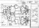
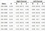
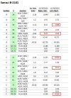
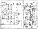
I went through the svc man and annotated it to make it easier for me to take measurements. I have attached it (see 2 attachments, PDF was too big to upload) and the actual readings I pulled from it (pls see the two attached tables- the 1st is of the power trans in place and 2nd is actuals for the values from Svc Man.). However, I do not know to what extent kVR3 and kVR4 impact these readings between the two channels.

Does anything stand out, such as the values I have in red? And, what are the suggested next steps for diagnostics? Start removing and testing the smaller transistors?

Any insight would be most appreciated as I am keen on enhancing my diagnostic chops.

Thanks in advance.
 

Attachments

  • 4618-4619-Schm-w-volts-1.JPG
    4618-4619-Schm-w-volts-1.JPG
    121 KB · Views: 16
  • 4618-4619-Schm-Flow-1.JPG
    4618-4619-Schm-Flow-1.JPG
    151.3 KB · Views: 17
  • 4619-Output-Trans_12-30-23.JPG
    4619-Output-Trans_12-30-23.JPG
    48.5 KB · Views: 16
  • 4619-schm-volts-actuals.JPG
    4619-schm-volts-actuals.JPG
    60 KB · Views: 14
Register to hide this ad
If i remember correctly the trimmers listed in part of the manual were incorrect like back to front maybe someone else can confirm has been a while since I had one to check…
 
Are you sure you're measuring on the correct pins?
kVR3 is measured on the two inner most pins on the left side.
Keep it on DBT until you know you have control over the bias procedure. It helps to see when the glow increases as you increase bias.
Set it to around 3mV on DBT and then switch to full AC to set the 6mV.
 
Are you sure you're measuring on the correct pins?
kVR3 is measured on the two inner most pins on the left side.
Keep it on DBT until you know you have control over the bias procedure. It helps to see when the glow increases as you increase bias.
Set it to around 3mV on DBT and then switch to full AC to set the 6mV.
MB and quadmatrix, thanks for the input. I now have spent a very considerable amount of time working this and seem to have gone back to the start.

Pls note the R channel is and continues to be set with the flipped trimmer issue understood.

I measured -1 volt on the good, R channel on the post trimmed side of the trimmer for the R side. When I adjust the trimmer on the L to match that value, again, the transistors are drawing way too much current and I have to reverse the trimmer to its original setting. Meltdown or component failure seems imminent.

So, the question is this - why are the transistors, affected by either KVR4 or KVR3, drawing too much current, when the bias is set to the 6.6 mv svc man. level? Something is different between the good R channel and this wonky L channel.

Also, this problem is isolated for the transistors managed by their respective trimmer.

I've Googled 'overheating transistors' and few speak to the actual causes, beyond speaking to bias settings. Ironically, it is attempting to set the svc man. bias that all hell breaks loose for the L channel, while the R channel remains my stable, 'good' part. So, why are these transistors drawing so much current? What are common reasons?

I also have tested and/or compared everything on 4619 between channels with the amp on and have tested all the components off power from the L channel, though in circuit, appreciating the compromises that dictates.

I would super appreciate any next steps to pursue.

If it means pulling the four Sanken trans pairs, 1386 and 3519, then so it goes. There are not that many components on the 4619 board and they all seem to check out while on board (diode testing for transistors and measuring resistors). I replaced the four alum. caps, so that is already done too.

Thanks, as always, in advance.
 
I don't understand what you're saying here with the measured -1V? You can't measure over kVR3 and think that will result in the correct setting, if that's what you're doing?
What do you measure in volts on the pins for kVR3?

1704647367559.png
 
I don't understand what you're saying here with the measured -1V? You can't measure over kVR3 and think that will result in the correct setting, if that's what you're doing?
What do you measure in volts on the pins for kVR3?

View attachment 3082733
MB:

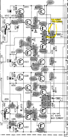
In the snip below, where the word "BIAS" appears is where I am measuring. In my reading of the schematic, the flow from the 4618 board 10/16 (the 3 wire connector from 4618), is managed by KVR3 and it is at that point on the board that the 1 volt measurement is being measured on the good side.

I wanted to follow the flow from 4618 thru 4619 to see if anything was obviously out of sorts on the bad board. I chose this as opposed to making my Nth measurement at the TP and seeing the near-zero MV for both Out Hot / Emitter hot and Out Cold and Emitter Cold (and then watching and smelling the heat increase as I begin to reach the 6.6 MV level).

A big question remains what is making the transistors pull the melt-down levels of current when the Bias for KV3 (or KVR4 for that matter) is set so the scv manual level of 6.6 MV? And, in the case of the good channel, the voltage at the word BIAS is 1 volt for both KVR3 and 4.
 

Attachments

  • 4619-A.JPG
    4619-A.JPG
    190 KB · Views: 7
That's the wrong spot. That's the location of the variable resistor you use to set the bias but not the point where you measure the bias.
I know it's difficult to get to those pins. Buy a suitable 5-pin USB header extension cable, it will fit.

Like this one:
 
Last edited:
That's the wrong spot. That's the location of the variable resistor you use to set the bias but not the point where you measure the bias.
I know it's difficult to get to those pins. Buy a suitable 5-pin USB header extension cable, it will fit.

Like this one:
MB:

Thank you for the reply.

I have a five pin cable from PC work and added hard pins for measuring at the 5 points (IT pack-ratting has its benefits). You may have mentioned something similar! This is what i used to set the good right channel.

I was looking upstream of that measurement point in an effort to ID the root cause of the hot transistors. Based on my reading of the schematic, it is at the point I noted above that adjusting the trimpots KVR3/4 impact the 4619.

The Base of Transistors Q27 and Q18 are fed by this point. Those are the small transistors on the outboard, underside of the alum. angle heat sink to which the big trans are heatsinked. Both of those transistors pass muster in terms of the diode test.

I believe, but may be wrong as I am no pro, that juicing the BIAS hits these two transistors which then cascades down through the board and similarly juices the 3519 and 1386 pairs. Any corrections or comments in this regard would be appreciated.
 
I re-read the thread.
Are you saying when you insert the original kVR3/kVR4 the left side is fine? What is the bias then?
And when you insert the new VRs and set kVR3 and/or kVR4 to 6.6mV the Power Transistors are too hot?

What work did you do on F-4619? Replace four capacitors, two variable resistors and re-paste the power transistors?
Did you take out the power transistors? Are they in the correct order? No legs touching metal?
Did you measure the 8 big white resistors?

It doesn't matter much what the transistors prior to the power transistors are doing related to the Power Transistors going hot IF the bias is 6.6mV.
If they go hot most likely the bias isn't 6.6mV and/ or you have a shorted transistors, a broken resistor or some other short.
 
I re-read the thread.
Are you saying when you insert the original kVR3/kVR4 the left side is fine? What is the bias then?
And when you insert the new VRs and set kVR3 and/or kVR4 to 6.6mV the Power Transistors are too hot?

What work did you do on F-4619? Replace four capacitors, two variable resistors and re-paste the power transistors?
Did you take out the power transistors? Are they in the correct order? No legs touching metal?
Did you measure the 8 big white resistors?

It doesn't matter much what the transistors prior to the power transistors are doing related to the Power Transistors going hot IF the bias is 6.6mV.
If they go hot most likely the bias isn't 6.6mV and/ or you have a shorted transistors, a broken resistor or some other short.
MB:

Yes to your question about one side being good and the other exhibiting the issues detailed above. And, yes to the minimal work done on the two 4619 boards.

Your commentary on the transistors is what I was looking for. Seeing that a bad transistor can work and not cause a DBT failure was eye opening for me, due to my lack of experience.

Will be pulling the power transistors and testing them - will let you know the results when done.

Thanks again for your time.
 
MB:

Yes to your question about one side being good and the other exhibiting the issues detailed above. And, yes to the minimal work done on the two 4619 boards.

Your commentary on the transistors is what I was looking for. Seeing that a bad transistor can work and not cause a DBT failure was eye opening for me, due to my lack of experience.

Will be pulling the power transistors and testing them - will let you know the results when done.

Thanks again for your time.
Thanks to the Hakko with a bigger tip and Peak atlas DCA75 Pro, I was able to remove and test each of the 8 transistors.

All checked out, with hFEs 102, 70, 88, 61, 66, 101, 49, 98. VBE matches fairly closely to what was measured with the 8 transistors in place at all around .6 volts with testing in Diode mode.

Conrad's thoughts that a DMM is pretty darn good at evaluating transistors in place bears fruit in this case. The full-monty testing with the transistors removed confirms they are not the issue, unless there remains some measurement that is not being revealed with the DCA75 Pro.

My next step is to substitute this 4619 with the good right channel 4619 and see if the 'unable to set bias without meltdown' issue persists. And, I'll swap this 4619 into the right channel location which did bias properly and see what things look like. At least this should eliminate some areas of debugging.

If anyone has thoughts, I am all ears.
 
Did you test the white 0.22 Ohm resistors?
Check kC30 and kC31 as well just in case.
You can also check so none of the legs now are connected to ground, should be quick with a DMM.

The bias current is verified by measuring the voltage over (some of) those resistors.
If the bias measures as 6.6mV there should be "no way" a larger current is running through some of those resistors unless you have a short or component failure somewhere.
You could also measure the voltage over each of those resistors to see it's same or similar.

1704763362444.png
 
FWIW, the left channel 4619 finally works.

I changed the c1845 (Q27) transistor and diode D8. (I already had changed D10.)

The orig Q27 hFE was 466; the new 389. I do not know if a 33% delta is material or relevant in this circumstance, but it is a data point.

DBTed the unit and 'Good to go'. Off DBT, let it warm up.

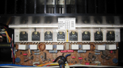
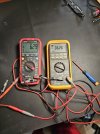
Connected a 5-pin pigtail, two DMMs, and adjusted the trimmers. As the photo shows, got bias tuned in. Whew.

I proceeded to replace all four diodes on both 4619s (only had 2 to go on left side).

It would have be great to change either the other diode (D8) and test and then swap out Q27 (or not), so only one variable was changed at a time. But, that is not how things worked out.

And, I forgot to add, all the diodes I replaced tested good using a DMM and the C1845 tested good on the Peak. So, add this scenario to others where components test good not 'in-situ' but are the root culprits.

Bottom line is the unit works and sounds super.

Again, appreciate the input from MB and quadmatrix82.
 

Attachments

  • 20240113_153545.jpg
    20240113_153545.jpg
    120.9 KB · Views: 7
Last edited:
Back
Top Bottom