


I have owned a Sansui B-2102 for about 5 years, and to be honest haven't used it much. I have given it a somewhat patchy restore, but there was a problem, not serious, with setting DC offset on one channel.
I had a few cracks at solving it when I have had time, so recently I decided I would have another go. My investigations focussed on one of the F-4618 pre-driver boards. I did a lot of comparing the Left and Right channel boards - which are identical, and changed quite a few components on the faulty one - without success. The problem showed itself by exhibiting too much DC offset (~240mV) on the offending channel, without triggering protection and after adjustment, it would creep down to less than 20mV over 10-15 minutes.
Yesterday I found the problem - a factory fit wrong value resistor on the faulty F-4618 board, fitted was a 1.2KΩ when it should have been 1KΩ. Note that I found the fault 'visually' just by studying the board closely.
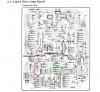
Here is the board layout - the wrong value resistor location (R41) is ringed in red - its opposite number (R42) is ringed in green.
And this is the schematic
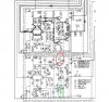
Notice how this balanced arrangement of components to deliver 0V at the output would have been influenced by a wrong value - thus unbalancing the circuit voltages and causing the DC offset setting with the trimmer VR1 to be incorrect. What made it difficult to find was that the wrong value was only slightly wrong, meaning that the difference could be adjusted out. But the tell tale was in the warm-up drift characteristic - plainly different when comparing channels.
That's all folks.
I had a few cracks at solving it when I have had time, so recently I decided I would have another go. My investigations focussed on one of the F-4618 pre-driver boards. I did a lot of comparing the Left and Right channel boards - which are identical, and changed quite a few components on the faulty one - without success. The problem showed itself by exhibiting too much DC offset (~240mV) on the offending channel, without triggering protection and after adjustment, it would creep down to less than 20mV over 10-15 minutes.
Yesterday I found the problem - a factory fit wrong value resistor on the faulty F-4618 board, fitted was a 1.2KΩ when it should have been 1KΩ. Note that I found the fault 'visually' just by studying the board closely.
Here is the board layout - the wrong value resistor location (R41) is ringed in red - its opposite number (R42) is ringed in green.
And this is the schematic
Notice how this balanced arrangement of components to deliver 0V at the output would have been influenced by a wrong value - thus unbalancing the circuit voltages and causing the DC offset setting with the trimmer VR1 to be incorrect. What made it difficult to find was that the wrong value was only slightly wrong, meaning that the difference could be adjusted out. But the tell tale was in the warm-up drift characteristic - plainly different when comparing channels.
That's all folks.
Last edited:


