• The move to the new server is done. There are some software and database maintenance updates in process. This has us passing the hat around to help out. We appreciate any donations. Seriously, even a dollar helps. The payment page may be found here - https://www.audiokarma.org/support.html

B&K EX-442 Rehab

Actually I finished up both amplifiers long ago. The 442 got all new heat sink pads as well as the 202. Both got new electrolytic's all the way thru and new B.R.. Everything was adjusted. DC and Bias on both amps looked like new with no measurable DC at the outputs.
 
Actually I finished up both amplifiers long ago. The 442 got all new heat sink pads as well as the 202. Both got new electrolytic's all the way thru and new B.R.. Everything was adjusted. DC and Bias on both amps looked like new with no measurable DC at the outputs.
Hi I have a sonata ex442 and was wondering can you share the steps you took in biasing your ex442, Like which pot is P1 and which is P2 and which fuse clips specifically did you place the meter across to read the 200~250 mA reading
 
Shoot me some pictures of the inside of your amplifier before I give you any details I want to make sure I am telling you the right stuff for your amp.
 
These may help. Not sure if your amp is set up like this one though. Look on the board and it should be marked as to what pot, P1 or P2 . I no longer use a 100 mV input signal or 8 ohm load resistors doing this either. I just pull the negative rail fused on the power supply boards and hang a meter across them then power on and let it sit for a good long while and adjust it to 250 mV. Setting the DC offset is really more important. Fooling with the bias can get you in trouble, but, you probably already know that.
 

Attachments

Shoot me some pictures of the inside of your amplifier before I give you any details I want to make sure I am telling you the right stuff for your amp.
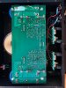
here's a shot of board top. I've marked which fuses are (-) and (+) when measured to grnd (chassis). When measuring across fuse that reads (-) i can adjust what is think is P2 and get a reading to 200mv, should it be set to 250 for the ex442 sonata? I think these are toshiba outputs and i read somewhere they should be set for 200mA verses having Hitachi outputs which are to be set for 250mA. Is this confirmed to be true do you know? When checking for offset how do i do that just put a vtvm set to dc across a speaker output? And if so does it need to have a load?
 

Attachments

  • IMG_6018.jpg
    IMG_6018.jpg
    129.5 KB · Views: 34
As far as I see you can only set the DC offset on that amplifier. No fuses pulled, meter set to DC mV setting. Simply put black probe on black spk output and red on red. Read mV reading on meter and adjust to the very lowest value. Repeat on the other channel. The blue pot on top of the board should be your adjustment . . Make very tiny adjustments and watch your meter of course. Before you do any of that have you already checked DC offset ? It may be fine as it is.
 
There are 2 blue colored plastic pots i adjusted the looking from front to back left side pot, using DC mV setting didnt see any change in reading displayed. God know what voltage that pot is adjusting.
 
Did you check the DC offset have the speaker terminals first ? If nothing moves almost pots at the terminals on your meter then those are probably bias pots pots. If they are bias pots you certainly do not want to turn those without watching the meter adjusted to milliamps DC across the bias resistors. That amp is like my ST 202 plus. It had a main board fastened to the main filter capacitors. The amplifier above in the picture I posted is an EX 442 The class A is built into the back to boards and there are two pots on each board One pot for DC offset one pot for adjusting the bias. If you turned one of those pots on either channel on that amplifier while measuring DC offset at the speaker terminal and there was no change then they are probably bias pots And you do not want to change the bias without being able to monitor it. That was what I was talking about in the post above. It's not a good idea to play with the bias unless you know exactly what you're doing. You can run some output transistors that way. Let me get home and check my documentation again we may need to start another thread or speak in a PM or otherwise in order to get this fixed.
 
One more thing I forgot to say I would not plug that amp back in or try to use it in any way until I found out for a fact that I had not changed the bias in the wrong direction. We have to get that checked before we leave the amp on for long long as you may have one channel overheat and it can overheat quite quickly.
 
OK I am back home by the PC now. Your amplifier is the same as my old ST 202+. The changes are only two more main filter caps, extra output transistors (Toshiba) and a main circuit board that is bigger/wider to accommodate the two extra main filters. I see no reason that you cannot pull the negative rail fuses on both channels one at a time and clip your meter in there set to DC mA (not DC mV) and set the voltage to 200mA. Keep in mind what I said earlier in the post. If the bias is not off then its best not to touch it. Also as far as I recall the ST-202+ did not have a DC offset adjustment. I think that was taken care of by an Op Amp on the mainboard.
The most careful way to do this is to set the one pot that you adjusted with no change on your meter back to where it was or if you did not mark it turn it middle ways and see what your reading is then. Move the pot till you get your 200mA reading. Please be aware of those big filter capacitors. I hope you know that they store around 70 V DC and that will really turn you inside out if you touch one of them and ruin some stuff if the short to any other part just about it in the amplifier. I hope I have not convoluted the issue farther. Please PM me if you need to talk.
 
One more thing I forgot to say. You can measure the channel you did not change for a reference if needed. After measuring that channel you can set the other one to the same DC mA setting and then at least you are in the ballpark.
Neither channel should ever read over 400 mA. If they do shut it all down and turn the pot down before you try again.
 
I am not going to lie to you I have misread just about everything here. I went back to the top to your first post and read on down now. For sure you have the amp and board set up just like (almost) my ST 202+ NOT my EX-442. The EX-442 has the four pots P1,P2 left channel and a P1,P2 on the right channel on the output boards to adjust BOTH Dc offset and Bias. You DO NOT have those. I see that now. The two pots on the solder side up of your main board are for BIAS adjustment NOT DC offset. Your amp uses Op Amps located on the back side of the main board to keep DC offset in check. This is not adjustable on your amplifier.
What to do... What I would do is this. I would unplug the amplifier. Make sure ALL FOUR big main filter caps are completely drained. Set that blue pot that you turned 1/2 way of the total turn. If the pot turns one whole turn then turn it to 1/2 of that rotation. I would not touch the other pot at all for now. We are only dealing with the pot that was turned before. Now, I would pull the left negative rail fuse. After that I would connect my meter across those fuse leads set to DC mA. See what you get. You should be able to set your bias now to 200 mA DC. If that works out GOOD, set the other side the same way. Unplug the unit, Drain the main filter capacitors, pull the negative rail fuse on the right side. Attach the meter leads and turn it back on check and adjust the other pot. If all that works well monitor the Right side bias. Let the unit warm up really good like 20min to an hour adjust to the 200 mA setting again if it has went up or down. If it stays steady you are golden, do the other side the same way. I always check the temp of my heat-sinks on my output boards as I do this bias adjustment stuff. If that heat-sink gets too hot to touch when you are doing this then you know you had best get that pot turned back down with a quickness. If not those output transistors are high dollar even if you can find them any more. Once again. If you need more info about this than we can type here PM me and I will try and help. I am a hobbyist not a tech so I don't know nearly everything a tech does. I do not do repairs for anyone besides myself. If that is what you wind up needing I am sure there are some really good guys here that can help. That is a super good amp by the way.

 
Last edited:
Back
Top Bottom