


likebike23
Addicted Member
I have a small Realistic SA-10 amp that I got for fun and it had a scratchy volume pot. I opened it up after a bit of fighting with it (tip: remove the bolts on the tone and right pot before sliding the PCB out of the back). I sprayed the pots with contact cleaner/lube and tried it out, it was better.
On reassembly, I guess I tried to hard to get it back in not realizing that the right Vol pot wasn't lined up with the hole on the front cover. Anyway, the right channel was faint with lots of crackling after that. I took it apart and saw that the pot was easy to wiggle. It has no support until it is seated in the front cover, I must have broken it when I slid the PCB back in.
At this point I'm looking for a new pot and all of the ones I see have 3 legs and I need one with 4 legs. A little googling and I see it is a pot with a loudness tap. After much searching for 100k volume pot with a Loudness tap, I find that RS has a dual gang one in stock at my local store. I didn't need a dual gang, but I had no other options so I picked it up.
First I desoldered the old pot and removed it from the board.
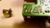
Next I dry fitted the new pot and saw that I would need to be creative with getting it in there. The new one is on the right.

I cut a section of cat5 cable I had hanging around and made some wire leads to solder to the leads of one gang on the pot. Turns out cat5 is a good choice as it has solid core wire that fits in the holes on the board easily.

Next I wiggled the pot into position and put the ends of the wire into the board.

I soldered it in (forgot to take a pic of that) and tried it out. Success! I carefully slid the PCB back into place and buttoned it up. The knob was not fitting, so I got out my drill bit guage and found the 15/64 size made a snug fit. I drilled out the knob to 15/64" and slid it on. Because the shaft was longer, I drilled all the way through the knob and touched up the silver from the shaft with a black sharpie.
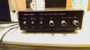
Thanks for reading this and if I made any errors in terminology it's OK to correct me. And if you see a better way or part, please feel free to suggest it.
On reassembly, I guess I tried to hard to get it back in not realizing that the right Vol pot wasn't lined up with the hole on the front cover. Anyway, the right channel was faint with lots of crackling after that. I took it apart and saw that the pot was easy to wiggle. It has no support until it is seated in the front cover, I must have broken it when I slid the PCB back in.
At this point I'm looking for a new pot and all of the ones I see have 3 legs and I need one with 4 legs. A little googling and I see it is a pot with a loudness tap. After much searching for 100k volume pot with a Loudness tap, I find that RS has a dual gang one in stock at my local store. I didn't need a dual gang, but I had no other options so I picked it up.
First I desoldered the old pot and removed it from the board.
Next I dry fitted the new pot and saw that I would need to be creative with getting it in there. The new one is on the right.
I cut a section of cat5 cable I had hanging around and made some wire leads to solder to the leads of one gang on the pot. Turns out cat5 is a good choice as it has solid core wire that fits in the holes on the board easily.
Next I wiggled the pot into position and put the ends of the wire into the board.
I soldered it in (forgot to take a pic of that) and tried it out. Success! I carefully slid the PCB back into place and buttoned it up. The knob was not fitting, so I got out my drill bit guage and found the 15/64 size made a snug fit. I drilled out the knob to 15/64" and slid it on. Because the shaft was longer, I drilled all the way through the knob and touched up the silver from the shaft with a black sharpie.
Thanks for reading this and if I made any errors in terminology it's OK to correct me. And if you see a better way or part, please feel free to suggest it.
Last edited:

