
• The move to the new server is done. There are some software and database maintenance updates in process. This has us passing the hat around to help out. We appreciate any donations. Seriously, even a dollar helps. The payment page may be found here - https://www.audiokarma.org/support.html

Balance control measurement

At this point, I don't think my output tubes can be trusted. I found two 6P14P-EV spares and put them in the left (humming) channel. They balanced up nicely and the hum is negligible..much quieter than what I had in there. And now having jogged my 256k memory, I remember swapping from two pairs of quads to find the quietest four earlier this summer. I remember being able to make the hum go from left to right by swapping outputs from side-to-side. So, if these are still quiet by morning, I guess my only remaining issue then would be the channel imbalance.

Edit - NOPE - left channel buzzing already.

Quick and dirty check, take a jumper wire and clip the two center terminals of the volume control together. If the imbalance remains, the problem is in the power amp section. If it goes away, its somewhere between input and volume control.

Do you mean center terminals at 9 and 3 o'clock jumpered together?
 
if the jumpers are in place and the wiring to them is still connected, then the 0.47 ohm don't matter. The jumpers are simply bypassing them. The point is you need a complete path to ground for the cathode circuit of the 7199. If the resistors and the jumpers are gone, its not going to work right.


Not sure the clock orientation on that specific pot, but most of them have 3 terminals close together on each layer, and usually a single terminal opposite that. Take the middle terminals in the group of 3 and clip them together. That will force the same input to both power amp channels even if the balance or the volume pot is screwy.
 
Thanks. I have enough speaker terminals to reconstruct the original setup
if the jumpers are in place and the wiring to them is still connected, then the 0.47 ohm don't matter. The jumpers are simply bypassing them. The point is you need a complete path to ground for the cathode circuit of the 7199. If the resistors and the jumpers are gone, its not going to work right.


Not sure the clock orientation on that specific pot, but most of them have 3 terminals close together on each layer, and usually a single terminal opposite that. Take the middle terminals in the group of 3 and clip them together. That will force the same input to both power amp channels even if the balance or the volume pot is screwy.

If I simply move each wire over one terminal on left and right from center of the terminal block, I can reconstruct the dampening circuit. Thanks!
 
Suppose...just suppose a certain absent minded 'professor', in a pinch, subbed a 5 watt 33 ohm power resistor on the 450 v. supply, rather than the 7 watt called for?

I intended to replace that with a 7 or 10 watt at the earliest convenience, yet it's still in there. Might it be responsible for the warm hum?
Just playing around tonight, I put a quad of 6P14P-K in, dialed the variac down to 112, and replaced a Copper Cap SS rectifier with a GZ34 to further drop voltages.
It's actually quieter now that it's warm, instead of the opposite.

Too many variables to assume? I just wonder if that resistor has been on the bleeding edge...
 
Doubt it. Its a fairly good bet the original 7w part was pushed pretty close to it's ratings. A 5w is probably beyond it. I'd use a 10w part to replace it.

Did moving the 7199 tubes do anything? How well matched are those tubes?

honestly I would be aiming for normal operating voltage. Whatever input voltage gets you 6.3vac on the heater line should be correct. Use the tube rectifier if thats what it had and see what the B+ is. if there is some way of monitoring output tube current, that would be useful to check. I think these do balance by nulling the hum out. Don't think there is a bias level adjustment or test point in stock form.
 
Yes, I did move 7199s around - same thing no matter what. Two Raytheon 7199 pairs were supposed to have been matched, as were a pair of Sylvania 6gh8
I'll start by putting the .47 ohm resistors back and go from there. I'll start taking some voltage measurements. I'm set up with 10 ohm resistors on the outputs, so I can measure current. At last check, measurements were inline, but it's been awhile. You're right, it has a null pot. Thanks guy...you're a patient man.
 
VICTORY! :banana:

Right hand 7199 socket: The 47K resistor on the left is soldered to pin one and the coupling cap going to the V9 output tube. The other lead of the same resistor sneaks under the 47K resistor on the right, and is soldered to a ground lug on the socket itself. The other coupling cap & the associated 47K resistor are soldered to pin 8. Somehow, a glob of solder got attached between pin 8 and the ground lug of the other 47K resistor, causing a short.

All of my issues are gone: Humming, hashy noise from the left channel, getting louder as the amp warms, and channel imbalance. I have full, glorious output on both channels.
I'm so darned happy. :bigok: Edit: Still doesn't like straight AC line voltage - left channels still hums there. Seems content at 115v. For another day.
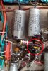
IMG_20190823_142233727.jpg
 
Last edited:
Back
Top Bottom