
• The move to the new server is done. There are some software and database maintenance updates in process. This has us passing the hat around to help out. We appreciate any donations. Seriously, even a dollar helps. The payment page may be found here - https://www.audiokarma.org/support.html

Beogram 5000 DIN wiring

kohngallery

New Member
I stupidly took apart the DIN wiring from the Beogram 5000 thinking it would be easy to install RCA turntable cables. It wasn't. I cut the wires inside the DIN connector and now want to resolder and use an adapter. But...I didn't take a photo and don't know which color wires go on which number pins. One of the black wires is a ground that is soldered to the metal shield. I think the yellow is a common ground for the L and R channels.IMG_7844.jpeg
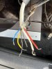
Can anyone help??!!
 
Register to hide this ad
The web seems to have 'answers' that one would need to have the unit to verify to be able to connect properly.

Seems there are two remote control wires that are extra to signal and then the signal set of 4 plus a ground. Expect common color code for the signal but not sure with Beo gear.
White is left hot, blue is left ground
Red is right hot, green is right ground

Hey where did yellow come from? That is sometimes a replacement for white. So with what you have, I would need to be there and have the www available to figure out what to check with a meter to verify.

Is that wire connected to the table? If so, you could meter the cartridge and verify the connection to the wire at the end. Then a DIN diagram would get you on the way of how to connect it.

Beoworld should have someone that knows how that is connected or modded to be RCA plugs.
 
The blacks are the signal grounds for each channel and both go to DIN plug Pin 2
Red is right channel and goes to Pin 5
White is left channel and goes to Pin 3
Yellow is Datalink and goes to Pin 6

Not sure about the blue!
 
Unfortunately it didn't work. The wire sheathing need to be grounded to something. I distinctly remember the black wire being soldered to the metal casing around the DIN. The second black wire doesn't exist as it is just threads (no wire) inside it. Any diagrams, photos of the original as it is connected??
 
Back
Top Bottom