


Ok so while AK was down over the weekend I cross-posted on the Beoworld forums - https://forum.beoworld.org/forums/t...2-15v-power-supply-not-activating/#post-71003 - and someone over there encouraged me to completely isolate the power supply from the rest of the unit.
I did that by lifting everything on the PCB that connects to the + side of C145.
With it all disconnected, still on the DBT, I now see 15V on the PS 95-99% of the time I turn it on.
I then re-soldered one thing at random to see what would happen. It was R168 which is a part of the FM field strength meter circuit.
With R158 back in the circuit ... the PS won't activate again. However instead of 0.06V, the 15V PS now shows around 1V.
On the Beoworld forum, there was a suggestion that the zener diode was not working. So I swapped ZD148 out for a new 9.1V zener (again) but ... no change.
What the heck?!?
So I took my second DMM and hooked it up from B to E of TR17.
Across TR17B - E, when the 15V PS doesn't activate, I only see 0.4V!

Here's where it gets weird again. If I turn it off then on again quickly, the 15V comes back.
Looking closely at the DMMs when I power it down, TR17B-E sees over 0.6V and activates while the unit is shutting down!! I snapped a quick pic as this happened:
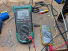
So WHY does TR17E-B only have 0.4V across it when R168 is back in the circuit?! Why does this happen more often with R168 in the circuit? And then see >0.6V when the unit is powering off??

I did that by lifting everything on the PCB that connects to the + side of C145.
With it all disconnected, still on the DBT, I now see 15V on the PS 95-99% of the time I turn it on.
I then re-soldered one thing at random to see what would happen. It was R168 which is a part of the FM field strength meter circuit.
With R158 back in the circuit ... the PS won't activate again. However instead of 0.06V, the 15V PS now shows around 1V.
On the Beoworld forum, there was a suggestion that the zener diode was not working. So I swapped ZD148 out for a new 9.1V zener (again) but ... no change.
What the heck?!?
So I took my second DMM and hooked it up from B to E of TR17.
Across TR17B - E, when the 15V PS doesn't activate, I only see 0.4V!
Here's where it gets weird again. If I turn it off then on again quickly, the 15V comes back.
Looking closely at the DMMs when I power it down, TR17B-E sees over 0.6V and activates while the unit is shutting down!! I snapped a quick pic as this happened:
So WHY does TR17E-B only have 0.4V across it when R168 is back in the circuit?! Why does this happen more often with R168 in the circuit? And then see >0.6V when the unit is powering off??
Last edited:


