• The move to the new server is done. There are some software and database maintenance updates in process. This has us passing the hat around to help out. We appreciate any donations. Seriously, even a dollar helps. The payment page may be found here - https://www.audiokarma.org/support.html

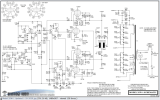
Beveridge 2SW-1 Amp Schematic

StatguyKT88

New Member
I have a pair of Bev 2SW-1 amps and the associated 'stat speakers that go with them and would like to
understand the operation of the circuit better than I currently do. The amps were designed by the late great Roger Modjeski. See below.

For any of you out that are familiar with this novel circuit using 36KD6 output tubes (it was novel in it's heyday-mid/late '70s, maybe still today), I would ask if you could give me an overview of the circuit's operation. I bought the system in '79 which were the store demos (the only way I could barely afford them) and I'm still not tired of them yet after 42 years.
Looking at the circuit, I'm mostly concerned with the circuit up to resistors R1,2,3,4 which connect to the grids/cathodes of the tubes which appear to be in bridge configuration. I believe Q107 is a phase splitter with its collector and emitter sending the negative halves of the signal to the cathodes and grid 3 of V201/203. Q108/9 and Q110/111 are the driver circuits for V202/204. I would like to understand more how pairs V201/202 and V203/204 operate together to produce the audio output which 'rides' on the diaphragm of the transducer which has +1650Vdc on it. As you may know these speakers are constant voltage transducers as opposed to constant charge type which all other 'stat speaker companies use. assessments

Please correct me if my assessments above are incorrect. The reason for all this is that I have very ambitious aspirations to convert the circuit that's upstream and to the left of resistors R1,2,3,4 from SE transistor to differential/balanced triode input using an Alan Kimmel Mu stage that I have from a paper he put out way back which describes the benefits of the Mu stage with various circuit configs. One of them is one which has differential inputs/outputs using a 12AX7 (or 6DJ8) and a 12GN7 pentode. Another circuit I saw was from a Chinese company that sells various pwb kits. One of them is a differential I/O circuit board using a 12AU7 followed by a 6DJ8. I would choose the mu stage over the other circuit. This would eliminate the phase splitter and I would reap the sonic benefits of a tube front end with balanced inputs which can drive the amplifiers directly. This would also ultimately allow me to hear the full potential of my Levinson CD Processor which has its own switchable preamp with balanced outputs.

The goal for me is to know if these circuits are adaptable to the Bev amp circuit perhaps with modification.

THANKS MUCH in advance!

Statman


Bev 2SW_1 Amp Schematic Redrawn.png
 
Register to hide this ad
Output tubes appear to be run in a mu follower configuration. Its a way to get relatively low output impedance while still having a lot of gain. Basically V202 and V204 are a standard pentode setup. Input on the grid, output on the plate. V201 and V203 are acting as a cathode follower. No voltage gain, but low output impedance. Since there is no DC path through the 'stat panels, the follower is also providing plate voltage to the tube that is actually amplifying signal. The electrostat panels represent only an AC load.

http://www.valvewizard.co.uk/mufollower.html

R1 and R3 I believe are your negative feedback connections. R2 and R4 are just a 1k grid stopper to keep it from amplifying radio signals and other nonsense.

If you replace the transistor front end, just make sure you provide some means of biasing the output tubes. Currently they are directly connected to Q108-Q111, which is the source for the -30v grid supply. You can cap couple that to the output of a tube driver and just use resistors to tie the grids to the bias source.
 
Gadget73 thanks so much for your response and help! I have some other questions for you on the Bev amp circuit and the Kimmel Mu stage tube circuit
I hope to use for a potential change to the circuit that we discussed earlier. I have attached the Kimmel balanced tube input circuit below for reference.

I plan on keeping the R128,129,131, C112,113,114, D101 network that supplies the -60V for the current transistor front end I want to replace. I will probably
wind up using 12AX7's over the 6DJ8's since they are higher mu and the 12GN7's. Could I just tap off -60V from the junction of R128/R129 as in the Bev schematic and divide it down to -30V using a simple volt divider (see R5 & R6 in attached schematic)? I also need to measure the voltage gain from the
input of amp to the collectors of Q110 /Q111 so I may duplicate this gain in the tube version circuit. Would it be safe to measure the peak-to-peak voltage with a high input impedance DVM? I can then convert this voltage to rms voltage or use my old Fluke 8050A which can measure true rms voltage. I can power up the amp and feed a 1kHz signal of say 100 or 200mV to the input of the Bev circuit just to get a an output to measure at the collectors of Q110/111. I have a dummy load I made up a long time ago (1.2K 10W resistor in series with a, .0047uF 6kV cap) which the late Harold Beveridge told me to use when I talked to him and connect this between the +electrode (red) and the diaphragm (black). Then this measured voltage would be duplicated between the grid of V1A and V3 output at Rsc. A question I have is measuring this voltage in the transistor circuit which is single-ended. Would this voltage in the SE circuit be half'ed in the differential tube circuit? I think the answer to that is no since by virtue of a differential circuit the two + and - inputs are equal in amplitude but out of phase by 180 degrees. Another question: Would RL/R2 and RL/R4 go away at the outputs of V3 and V4, having their outputs connect directly to the Grid1's of V202/V204? One last question: in the tube input circuit, are R1 and R3 NFB lines to the plates of V2A and V2B the appropriate points to apply the NFB?

Whewh. That 's it. Sorry for all my questions. I'm too eager to try this out- so I can at last hear the balanced outputs of my CD player driving a balanced input, all-tube Bev amp. I read in an old Stereophile review I have of my player that going from SE outputs to the balanced outputs are just about a night and
day difference.

Thanks so much again!

Statguy
 

Attachments

I know this is strange getting back to the items I mentioned in my post from over 2 years ago regarding replacing the transistor driver circuit in my Bev amps with the balanced I/O driver tube circuit attached in that post (see above dated 2/28/21) but I still have a crucial question from that post. Is neg FB still required when using the balanced tube circuit? If so, where and/or how should the neg FB resistors, R1 & R3 (7.5M), be connected in the circuit? What additional circuitry would be required if needed? V1 & V2 are 6DJ8s and V3 & V4 are 12GN7s in the balanced circuit. I attached the Bev amp and balanced tube schematics again for convenience. Thnx.
 

Attachments

feedback will generally give you lower distortion, flatter frequency response, and lower output impedance. No idea what the impedance swing is like on these but pentodes aren't great for output Z. The mu follower setup helps but with feedback it will still be lower than without it.

as to where to bring it in, probably to the cathodes of the first tubes. Gonna need a DC blocking cap since the cathodes are negative DC and the output is a bunch positive. Ideally some measurements would have been made to figure out how much feedback was originally applied so you have an idea how much it should have applied.
 
I should have mentioned that I was aware of the benefits of feedback and why it's used for the reasons you mention. I just wasn't sure exactly where to apply it in this case. In the white paper Alan Kimmel authored back in '93, who also penned the circuit (and many others), stated that using a 6DJ8 as the bottom tube and a 12GN7 pentode on top with a 1000uF cap across a 1K ohm resistor which is tied from cathode to gnd of the 6DJ8, a typical Zout @ 1kHz is 100 ohms which he measured. Without the cap it would be 346 ohms. Also, going to a higher transconductance pentode lowers the Zout further. Of the pentode tube candidates he suggested, the 12GN7 had the lowest Zout.

Yeah per Kimmel's paper the cathodes of the first tubes need to be at least -100Vdc (I'm using -120V). I forgot about the needed dc blocking cap. I've seen this cap value to be in the 200 to 300pF range in other circuits. It would have been nice to to know how many dB's of NFB were used in the Bev amp. I will try tying the 7.5M resistors to the cathodes of the first tubes.

Thanks much for your help and quick response!
 
gonna depend on the value on the cathode resistor. Have to figure that the cap has an impedance that increases as frequency drops. That number working into the cathode resistor value will roll off at some point. If its too high, it will end up providing a bass boost which you probably don't want, and it gets into phase shift issues which can cause stability problems. I think you'll find it wants to be a fairly large value so it doesn't add any significant amount to the fixed resistor down at the bottom.

The 7.5M also may not be the right value for the same reason. Stock its working into basically 260k, if those new cathode resistors are smaller, a rough ballpark starting point might be to change the 7.5M so its still proportional. No guarantees it will give the same feedback level since thats going to depend on the open loop gain now vs stock but at least the voltage amount will be the same.
 
Referring to the balanced I/O driver circuit, I will be setting up one of the two 300V windings of it's pwr xformer to provide a well-filtered and regulated ~ -110 or 120V(?) to the cathodes of V1A and V1B using a reverse-biased diode and -30V reference zener diode. In the Kimmel paper the resistor value shown in a similar circuit to the one I am using is 1K for the Rk1 value. This similar circuit is a SE input connected to both grids which are tied together as well as their cathodes of the 6DJ8 which drives a pentode top tube. It also shows a 1KuF cap in dotted lines tied across Rk1 to lower the Zout of the pentode. In the balanced input config of the circuit I am using I don't know if both Rk1's could/should be 1K(?). I was going to try it. The tube portion of the Bev amp has a 3rd order crossover network before its driver stage which begins to roll the stat panels off at 100Hz where a separate subwfr amp takes over from there down to 20Hz. So as you mentioned, I do not want any bass boost. I see what you are saying about the Z of the cap getting too high causing this to happen. Could you guesstimate a cap value to try to start with?

For what it's worth I measured the DC volts at the 7.5M where it ties to Q108 base and it is -2.5 to -3.0V which I guess doesn't matter. I suspected that this resistor value may/would not be the one to use. I would presume by what you are saying that this resistor should become smaller if Rk1 = 1k
but by how much? I don't think the 7.5M's should get too much smaller safely since there is +1600 volt on the other end of them. I measured and calculated the voltage gain from driver board input to Q110 collector and it's 28 which must be maintained. I have read for this amp (but not measured) that there is no gain from that point to the tubes' outputs. As mentioned I would not know the open loop gain. I know that as the NFB is increased the overall gain will be decreased trading gain for better linearity,etc.
If I do use 1K for both Rk1's, what value resistor would you suggest to try out? Would 7.5M - 250K = 7.25M (or closest standard value) be a fair guess?
Thanks again.
 
Without knowing the value of the cathode resistors, I have no idea how big the cap ought to be, but the smaller the resistor, the bigger the cap has to be to maintain the same roll off points.

Same with that 7.5M resistor, stock it works into 260k, if you run it into 1k the amount of feedback signal that appears at the cathode is going to be extremely small to the point where it may not be enough to actually do anything useful. The DC voltage doesn't matter for the resistor, thats what the blocking cap is for, but that number will matter when it comes to picking a capacitor. If its sitting at 1600v DC, I'd probably want at least a 3kv cap there to account for AC signal peaks. Getting a high value at that voltage is going to be pretty difficult.

but to use the example if the stock value is 260k and you make it 1k, 7500k / 260k = ~29 so the feedback resistor would need to be 29x the cathode resistor, or 29k to keep the same voltage ratios. It may be nowhere near the right value to actually maintain the stock feedback level, or maybe you don't even want to maintain the stock level. Thats really why knowing the stock level would be key to all this, its pretty much a guess without either an accurate simulation or a measurement. I never figured out how to get simulations to work so I just pretend like its 1960 and measure stuff.
 
Back
Top Bottom