


RemoWilliams
Addicted Member
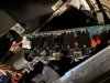
Looking inside it appears that BGW mounted the 1/4" inputs on a board, along with the balanced input / outputs and the stereo / mono switches. Model is the GTB.
Apparently schematics are difficult if not impossible to find though I wonder if one could at least simply desolder the balanced and unbalanced from the board and hopefully trace the wires on the multi pin connectors, finding the unbalanced + and - and then soldering them to some replacement RCA inputs.
Of course, I could simply continue to use the 1/4" to RCA adapters that I have, there are some decently made ones available but simplifying the signal path is tempting. Not well versed in electronics unfortunately but can do the basics.
I can't say the system sounds off or un engaging - using KEF 105.1 and the two BGW power amplifiers certainly do a good job ( the GTB is for the 12" driver and another BGW for the mid / tweeter ).
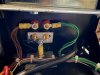
Unfortunate that it was not an easier modification. Looking at the speaker binding posts not sure if I should bother replacing them, was going to solder the wires directly but a bit too hefty plus I see they used a common grounding point as well. Maybe some copper ring connectors instead of the aluminum ones?

Apparently schematics are difficult if not impossible to find though I wonder if one could at least simply desolder the balanced and unbalanced from the board and hopefully trace the wires on the multi pin connectors, finding the unbalanced + and - and then soldering them to some replacement RCA inputs.
Of course, I could simply continue to use the 1/4" to RCA adapters that I have, there are some decently made ones available but simplifying the signal path is tempting. Not well versed in electronics unfortunately but can do the basics.
I can't say the system sounds off or un engaging - using KEF 105.1 and the two BGW power amplifiers certainly do a good job ( the GTB is for the 12" driver and another BGW for the mid / tweeter ).
Unfortunate that it was not an easier modification. Looking at the speaker binding posts not sure if I should bother replacing them, was going to solder the wires directly but a bit too hefty plus I see they used a common grounding point as well. Maybe some copper ring connectors instead of the aluminum ones?
Last edited:


