• The move to the new server is done. There are some software and database maintenance updates in process. This has us passing the hat around to help out. We appreciate any donations. Seriously, even a dollar helps. The payment page may be found here - https://www.audiokarma.org/support.html

Bias level adjustment - Crown DC-300A II

donberry

Super Member
sort of a double post, was just hoping maybe some more eyes would see this.
Crown DC-300A series II amp. Trying to do the bias level adjustment. in the service manual, does not really say where to take the measurements, just mentions the base-emitter.
On the amps up to serial number 81323, there is a resistor you change to set the bias and you measure the current at R132, R139 and R232, R239 - but on amps with serial number 81324 and higher, which I have, there is no R139 or R239 on the output boards, or the main board from what I can see.
The Service manual does not have a schematic for the output boards, just a parts list, and in the parts list for serial numbers 81324 and up, the resistors start at R300 - no R129 or R239 to be found.

So, I ended up taking the reading directly off of the output transistors and adjusted the dc to .31 per the manual. I just could not figure out where to take the reading. Thought it was all figured out, took the readings from the output transistors, dialed right in to .31vdc.

re-checked it after an hour and still maintained the .31vdc.
Hooked it up. Thought all was well. Was playing some kids music(mp3's) for my grand daughter, turned it up a little and one of the speakers made a real loud POP, sounded like a gunshot - was not cranking it at all.
Scared the bejeebers out of grand daughter and one of the dogs.
Tried it again, same result - no meters, but i am guessing the peaks were still under 30 watts.
So, I am guessing I did not adjust the bias correctly ? Or it needs some other work done on it ?
Doubt it is speakers as I have been using them for a while and have had them at least twice as loud as i was playing tonight.

anyway - is taking the readings on the output transistors right ? If not, anyone have any idea where you take the readings as there are no R129 or R239 on this series of amp.
Thanks for any info, sorry for double posting - is just driving me nuts
 
Register to hide this ad
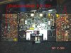
In the service manual page 36 , fig.6.5
 

Attachments

  • DSC02934.JPG
    DSC02934.JPG
    99.6 KB · Views: 114
  • DSC02935.JPG
    DSC02935.JPG
    58.5 KB · Views: 105
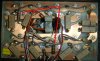
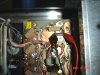
Measure across one bias resistor on each channel, it doesn't matter which resistor.If you get a negative voltage just swap the test meter leads.Illustration is for one channel the other channel is on the opposite side of the unit..But you knew that...:D
 

Attachments

  • DSC02937.JPG
    DSC02937.JPG
    83 KB · Views: 80
Last edited:
I caution you on making adjustment assumptions without the proper documentation and/or experience. In the absence of experience, documentation is a must (IMO). that "0.31" voltage that was in the manual.... .....you can't adjust according to that. Transistors are current devices, not voltage devices. That "0.31" Vbe is just a typical reading and not an adjustment quality value. The correct location to make an output section bias meaurement is across an emmiter resistor. Bias keeps the transistors on a little bit more than the output signal itself. So, you want to measure DCmV across an emmiter resistor under no signal conditions. To do this per the factory spec, you'll need the mV value of what should appear across an emmiter resistor. Bias adjustments are not to be taken lightly. A misadjustment can cause amp failure.
 
I caution you on making adjustment assumptions without the proper documentation and/or experience. In the absence of experience, documentation is a must (IMO). that "0.31" voltage that was in the manual.... .....you can't adjust according to that. Transistors are current devices, not voltage devices. That "0.31" Vbe is just a typical reading and not an adjustment quality value. The correct location to make an output section bias meaurement is across an emmiter resistor. Bias keeps the transistors on a little bit more than the output signal itself. So, you want to measure DCmV across an emmiter resistor under no signal conditions. To do this per the factory spec, you'll need the mV value of what should appear across an emmiter resistor. Bias adjustments are not to be taken lightly. A misadjustment can cause amp failure.

Amen to that........
 
avionics - I hope u did not have to go to the trouble of taking those pics just for this? Couldn't thank u enough as it is - sort of like having you sitting here doing it for me.
We know I am not that bright, but I never even saw that schematic on page 36 - to be honest, when I read your post and saw "page 36..." I was thinking we must be in different manuals as page 36 is my last page.....
is what happens when you start helping us "iliterates"
Thank you so much....
side note - actually just notice you were retired air force. I did not do 20, but I am retired Army(disability). I was young and stupid, thought I would have some "thrills", took me about one year to realize I should have joined the air force - :yes:
Jon-
HTML:
I caution you on making adjustment assumptions without the proper documentation and/or experience
I really do appreciate the comment and I know that you are 100% correct, but now, probably unfortunately, I have the mind set that on most things, I am going to try to tackle them first, full well knowing I could end up with boat anchors and being very careful not to electrocute myself(wow, this Crown packs a wallop)
Now I have always been a tear it apart , fix it myself kind of guy. Often end up spending more then if I would have if I paid someone else to do it - cars, home repairs, lawn mower, computers - if I own it, I have done the repairs on it and screwed something up , some things beyond repair, sort of a jack of all trade, not even close to a master of any.
20+ years ago, I did repair inertial guidance systems for missiles and f16's, but have pretty much forgotten everything I know due to some heavy, legal , prescribed drug use.
When I first starting getting vintage equipment, I found AK of course. Had some pieces I needed repaired and was looking for a tech as I had never seen the inside of an amp etc before and had(have) no idea how they worked. Got a bunch of responses that were basically saying I need to get my hands dirty and learn to do it myself - and alas, my rusty wheels started spinning and I thought "why not, I tear everything else apart, how hard can it be".
Found out I must have lost a few billion brain cells along the way, but I accept the fact that I may lose a few pieces along the way, actually am REALLY hoping I have not screwed up my Spec 2 too awful bad,
BUT, they were correct. I am learning more and more, the rust is still caked on, but I am SLOWLY understanding more and more and my schematic reading ability is SLOWLY coming back(tho is a heck of a lot different then a PIG(pendulous integrating gyroscope) and the gyroscope for a F16 that I used to be pretty proficient at (those were more straight line schematics -just follow the line thru the thousands of wires)
anyway - (see, my drugs are kicking in so I ramble), I have accepted the fact that I may have some cool paper weights, but slowly, ever so slowly, piece by piece, I am getting more comfortable - fortunately there are some really patient guys around here that point me in the right direction (how unbelievable is it that avionics took those pics, is that cool or what)
just keep an eye out, may be a cheap non-working Crown and pioneer Spec 2 for sale lol - nahhhhhhhhhhh :music:
 
Last edited:
1 - a HUGE shout out to avionics for taking the time to get pics to point an idiot like me in the right direction.
2. fwiw - letting it warm up to be 100% positive, but I am getting the same reading on the bias resistor(pointed out by avionics) as I am getting on the output transistor itself, so I may have sort of stumbled in right direction unknowingly - tho I do believe the resistor needs changed. Need to shut it down to double check resistance.
Value has changed since setting it yesterday. was .31vdc, today reading around .345 and .335
 
Your voltage(bias) measurement is very temperature sensitive and may drift up and down. Key is to get as close to the center value so your drift is still within tolerance.If it still drifts way out of tolerance you probably have output transistor voltage leakage.
 
Last edited:
ok, believe it is all done. As mentioned above, turns out the voltage measured across the output transistors is the same as measuring it at the bias resistors.
Resistor is supposed to be 5.6, comes in at 6.2 - not bad considering carbon resistance tends to rise with age. I am going to replace them here very shortly, trying to decide what resistor to use. tempted to use a wire wound as there are only 4 of them, still undecided on pros and cons. Obviously ordering caps too.

Voltage seems to drift up some - have to recheck it again here shortly, but from yesterday it went from .31 up to about .345, pretty much same on both sides.

As it is not a complicated board, will probably just go ahead and rebuild both output boards, replace everything on them. Torn between using the sand cast wire wounds like it has on it or the more expensive ones like silicone. As there are 18 of them (9 per board), would be a pretty decent price difference, but probably be an amp I keep as I only paid $125.00 for it and am hoping to use it along with Spec 2 to biamp the magnepans. Just have to research a little to figure out if the sonic difference would be anything i would notice(I am guessing not)

Speaker pop - actually speaker still does it, but now leaning towards it being the speaker. tried a different preamp to rule that out. Did not think it was, but never know. Then finally made up some banana clip ends instead of fighting to move the speaker wires around - switched the wires around and it still did it out of the same speaker. I could be wrong, as I often am, but i would have thought if it was the amp, the pop would have moved to the other speaker.

Will probably do this in stages as i am using it now, but next month will just go ahead and probably redo most of the main board to. Was reading a post on DIY about a rebuild, but it was a series 1 so there are some differences, plus, without a scope, not sure about changing out transistors. Seems most of them are still obtainable, though a couple, like the NSD128 are no longer available. Last time I tried replacing one, I put a ECB in a EBC on my Spec 2, which is why my Spec 2 is down and out at the moment, so need to be careful there.
But hopefully i learned a valuable lesson from last time (READ THE DATASHEETS CAREFULLY-lol).

anyway, long as usual. Need to move some different speakers in to check it out, but at normal listening levels, not shrilly highs at all like many have talked about, actually sounds pretty good all things considered.
Can't thank u enough avionics for taking the time with me, even getting the pics. It is people like you that have prodded me along and given me the courage to jump in and do it myself to begin with. Help like that is invaluable and probably appreciated more then you know. Gives us budget pocket book guys a chance to build a decent stereo and satisfy our audio needs, plus also gives us guys (and gals) a chance to learn more about what is going on under the hood. As mentioned previously, often has cost me more in the long run repairing/restoring things myself, but for me, is a much more satisfying experience knowing I did it myself(with everyone's help here of course) Well worth that feeling even if it does mean an accident here or there.

But when i do turn things into a boat anchor, of course i am going to blame you :D

Thanks for all of the help, if ever anything I can do for you, maybe paint something or parts etc.....give me a shout.
 
Back
Top Bottom