• The move to the new server is done. There are some software and database maintenance updates in process. This has us passing the hat around to help out. We appreciate any donations. Seriously, even a dollar helps. The payment page may be found here - https://www.audiokarma.org/support.html

Bias of Realistic STA-2300

pjrengineer

Simpler times
Subscriber
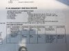
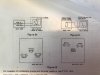
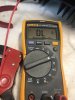
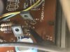
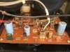
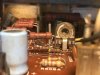
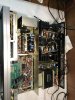
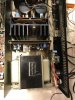
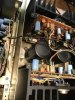
I am adjusting the bias of the realistic sta-2300 and must be doing something wrong. See photos. I am not getting a mV reading but a 117v reading.

when it says measure across the emitter resistors, does that mean positive lead left side of r513 and negative lead right side of r515?

I have an 8ohm load connected to the speaker terminals and speaker A on.
 

Attachments

  • 4F6023CB-C73D-409F-B452-2AC7FCFB49D5.jpeg
    4F6023CB-C73D-409F-B452-2AC7FCFB49D5.jpeg
    77.3 KB · Views: 20
  • 6C4CEA20-2965-4D2A-9B58-06BD4EB1C1D2.jpeg
    6C4CEA20-2965-4D2A-9B58-06BD4EB1C1D2.jpeg
    57.8 KB · Views: 19
  • BDCF17B6-2108-48B2-8858-2AE97DA68FB5.jpeg
    BDCF17B6-2108-48B2-8858-2AE97DA68FB5.jpeg
    52.3 KB · Views: 20
  • 1F9AA603-51CD-4C27-B842-56C4984B0E7F.jpeg
    1F9AA603-51CD-4C27-B842-56C4984B0E7F.jpeg
    74.7 KB · Views: 19
  • 35402C80-0E0A-4F00-A48A-5F85E2A09BD8.jpeg
    35402C80-0E0A-4F00-A48A-5F85E2A09BD8.jpeg
    72.4 KB · Views: 16
  • 0F959E8C-B1CE-403D-AE0D-6FC14400BD53.jpeg
    0F959E8C-B1CE-403D-AE0D-6FC14400BD53.jpeg
    90.9 KB · Views: 17
  • 5D9EBCF3-2EC9-4AED-A88B-373ED4213272.jpeg
    5D9EBCF3-2EC9-4AED-A88B-373ED4213272.jpeg
    69 KB · Views: 20
Register to hide this ad
The way it is done is to measure the mv across each resistor. pos on 1 side of R513a and - lead to the other side of R513a. Then you can check the pos and - on R15a but it should read the same mv as across R513a. Then you do the other channel measuring first across R513B, and after that, verify the same mv reading across R515B

Disregard the above as there appears to be many misprints in the service manual. This receiver has 4 outputs per channel, and 4 emitter resistors per channel.
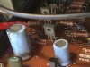
The easiest way to set the bias is to measure the mv across the white porcelein 5w 0.47 ohm resistors. (emitter resistors). I would suggest setting them at 9mv to 10mv per resistor. Basically set on, and verify that the others look close to the 9mv to 10mv as well. Then do the same for the right channel.
Those resistors are marked as R526a, R528a, R527a, and R529a for the left channel, and R526b, R528b, R527b, and R529b for the right channel.
 
Last edited:
The way it is done is to measure the mv across each resistor. pos on 1 side of R513a and - lead to the other side of R513a. Then you can check the pos and - on R15a but it should read the same mv as across R513a. Then you do the other channel measuring first across R513B, and after that, verify the same mv reading across R515B

tom thanks so much for responding. I tried that and still got high volts. I can’t figure it out. Maybe I disconnected some ground when I took the bottom cover off? I’ll try it again though just to double check.
 
tom thanks so much for responding. I tried that and still got high volts. I can’t figure it out. Maybe I disconnected some ground when I took the bottom cover off? I’ll try it again though just to double check.
See my corrections above

I thing they were trying to say measure MV from the "Emitter" of "TR513A, and the "Emitter" of "TR516A", or the Emitter of TR513A measured to the emitter of TR515A.

But its a lot easier to just check across each emitter resistor.
 
The way it is done is to measure the mv across each resistor. pos on 1 side of R513a and - lead to the other side of R513a. Then you can check the pos and - on R15a but it should read the same mv as across R513a. Then you do the other channel measuring first across R513B, and after that, verify the same mv reading across R515B

Disregard the above as there appears to be many misprints in the service manual. This receiver has 4 outputs per channel, and 4 emitter resistors per channel.
The easiest way to set the bias is to measure the mv across the white porcelein 5w 0.47 ohm resistors. (emitter resistors). I would suggest setting them at 9mv to 10mv per resistor. Basically set on, and verify that the others look close to the 9mv to 10mv as well. Then do the same for the right channel.
Those resistors are marked as R526a, R528a, R527a, and R529a for the left channel, and R526b, R528b, R527b, and R529b for the right channel.

I knew better. I should have trusted my instincts but don’t really know how to read a schematic well enough yet to determine how you did. But yeah, big ceramic I knew were the emitters.
 
Sounds great.
 

Attachments

  • 75570541-2B69-4C3C-ACD4-27A00180176A.jpeg
    75570541-2B69-4C3C-ACD4-27A00180176A.jpeg
    72 KB · Views: 12
  • 87C779A0-1D02-45C6-9F4B-7BEBC38721CA.jpeg
    87C779A0-1D02-45C6-9F4B-7BEBC38721CA.jpeg
    68.5 KB · Views: 12
  • C5057063-E4EB-49B0-96A0-A268D13E0708.jpeg
    C5057063-E4EB-49B0-96A0-A268D13E0708.jpeg
    70.9 KB · Views: 12
  • 366757EA-4415-47FB-B16B-C48607C9B671.jpeg
    366757EA-4415-47FB-B16B-C48607C9B671.jpeg
    72.2 KB · Views: 12
  • 6B9B1ACC-ADF7-477A-8453-349EE94159D2.jpeg
    6B9B1ACC-ADF7-477A-8453-349EE94159D2.jpeg
    66.2 KB · Views: 11
Back
Top Bottom