• The move to the new server is done. There are some software and database maintenance updates in process. This has us passing the hat around to help out. We appreciate any donations. Seriously, even a dollar helps. The payment page may be found here - https://www.audiokarma.org/support.html

Bias supply for Dynaco ST70 replacement power transformer?

Dandy

Addicted Member
As my mains voltage is 240V and the original Dynaco ST70 is under-rated, I would like to replace it with a massive PT that I have from an unknown 6L6 organ amplifier.

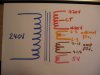
It is the exact chassis size and has the right windings for B+, 5V and 6.3V but no winding for the 55V bias supply. There is a 12.6V filament winding that was routed out of the power amp to another part of the organ.

As the PT is huge, I don't have any doubts about current supply, but I need to find a way to add the 55V bias voltage. What would be the best way? Thanks for any suggestions. I attach a wiring diagram of the replacement PT.IMG_0432.JPG
 
Register to hide this ad
I would use either a 24V - 120V transformer connected to the 12V winding which gives roughly 60V out, or a 12V - 120V transformer connected to the 6.3V winding which will also give ~60V out.

It does not need to be a very big transformer since the bias requires very little current. The one I use is about the size of a ping pong ball, give or take.
 
Thanks. Simple and elegant! And I have exactly that transformer, rated at 3VA, in my junk box.

Now I'm looking forward to hearing my ST70 kick up a notch.
 
Last edited:
It's late and I'll only get to this at the weekend, but can I just check: given that the ~50V supply goes to a single eyelet on the VTA board, does the other side simply go to ground? I don't have the VTA board schematic to hand.
 
Personally i would not replace a marginal transformer with an unknown that lacks all needed windings.
If anything i would buy a replacement from dynakitparts if, and that is a big if, the original transformer cannot keep B+
upp to spec. If on the other hand the original does keep up the B+ then one must ask "why bother changing ?"
 
You can use a capacitor into a diode then a resistor to the center tap from one side of the high voltage winding. You could use a 0.18uF 630V capacitor and a 27k 3W resistor. The bias voltage would be taken from the top of the resistor, into a diode, remember to orient the diode with the white stripe towards the resistor. Take a look at how Shannon does it on the IKE (EIClone) amplifier at www.DIYTUBE.com, he uses this set up and it works great.
 
Personally i would not replace a marginal transformer with an unknown that lacks all needed windings. If anything i would buy a replacement from dynakitparts if, and that is a big if, the original transformer cannot keep B+upp to spec. If on the other hand the original does keep up the B+ then one must ask "why bother changing ?"

It's not only that the original is under-rated, it's also because I want to use a 240V primary transformer--which I already have and which fits the chassis exactly. Sorting out the bias voltage is easier, and a lot cheaper/greener than buying a replacement from the USA.

And, I must admit, it's also fun.
 
It's late and I'll only get to this at the weekend, but can I just check: given that the ~50V supply goes to a single eyelet on the VTA board, does the other side simply go to ground? I don't have the VTA board schematic to hand.

That's how I did mine with VTA board and the "backwards" transformer for bias.
 
How about a voltage quadrupler? Bias supply needs very little current, you could step up that 12.6v supply sufficiently to get the job done.
 
I would use either a 24V - 120V transformer connected to the 12V winding which gives roughly 60V out, or a 12V - 120V transformer connected to the 6.3V winding which will also give ~60V out.

It does not need to be a very big transformer since the bias requires very little current. The one I use is about the size of a ping pong ball, give or take.

My experience is that this method works well, but running the transformer backwards is only about 85% efficient for a 6.3V to 120V transformer, and 89% efficient for a 12.6V to 120V transformer. So actual voltage out using the latter will probably be about 53VAC. So that's almost an exact match of the 55V bias winding on the original.
 
The backwards transformer in my Bogen gets me 90 vac out of a 120v primary, so ~75%. probably depends somewhat on the transformer, the one in the Bogen is a wee little thing.
 
It's not only that the original is under-rated, it's also because I want to use a 240V primary transformer--which I already have and which fits the chassis exactly. Sorting out the bias voltage is easier, and a lot cheaper/greener than buying a replacement from the USA.

And, I must admit, it's also fun.
Well spoken !
 
My experience is that this method works well, but running the transformer backwards is only about 85% efficient for a 6.3V to 120V transformer, and 89% efficient for a 12.6V to 120V transformer. So actual voltage out using the latter will probably be about 53VAC. So that's almost an exact match of the 55V bias winding on the original.

53V is exactly what I get from it connected 12.6-120V at the moment. But this is with the transformer unloaded. I expect all the other voltages to drop under load, but as this is a separate winding, it'll be interesting to see if it drops.

Hi-FiGuy, thanks for your alternative suggestion. I did something like this when I built a 7591 amp, again with a PT that did not have a bias winding, using the VTA board. That'll be plan B.

Thanks for the suggestions and advice.
 
The DC resistance of the HV winding will give a clue to its current capacity - should be lower than the original Dyna. Since the 12.6V winding won't be used, you might as well use it for bis. A tripler will give about -53VDC, quadrupler about -65.
 
Thanks for that simple guideline Tom. I'll measure it. So far, I'm just going on the size of the lamination stack, about twice the height of the original. I'll take and post some pics. I added the VTA board years ago, when I knew even less than I know now, so I intend to do a bit of tidying up too.
 
Tom, thanks again for your advice. My intended replacement measures 58 ohms, compared with the Dyna's 67 ohms. It's a relief to learn that it should be lower. Before checking your message again, I feared that it should be higher. So, I'll get on with the installation tomorrow.

I also want give credit to Roy Mottram of tubes4hifi.com. I bought the upgrade board I'm using in this amp from him about 10 years ago and he's just sent me a replacement copy of the relevant upgrade kit manual and schematic. What great customer service!
 
Last edited:
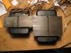
The PT is installed and works fine. Here's a pic of the replacement alongside the original.
IMG_0433.JPG
But ... with the wall voltage of 244VAC, I can't get the B+ down enough, even using a 5RVG rectifier to drop 67V. So, it's bucking transformer time, which slightly defeats the purpose of replacing the PT.
 
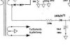
I had the same situation, i.e., I had a large HP power transformer which had all the voltages I needed except for the bias. I derived a negative bias voltage with a half wave diode from one side of the secondary high voltage winding. With a little fiddling of resistor values I got the value I needed without an additional transformer. In my ST-70 the first resistor is a 33k 2W and the cap is 100uF @ 100v. Don't remember the bias voltage that resulted but I got the bias I needed for 50mA in each 6p3s output tube. If you are using the original EL-34's you might need to tweek the resistor value. I fed the original bias pots from the cap/diode junction.

A voltage multiplier from the 12.6v winding is a good idea as well but takes a few more parts.

420V on the B+ secondary will be a bit high. You could end up with well over 500V of B+. EL-34's can take that I think but you might want to recalculate the bias current for the higher voltage to keep from over dissipation of the plates. Probably will also need to adjust some resistor values to get the voltages correct for the driver and front end stages but that shouldn't be too difficult.

One problem I had with the oversize power transformer is that when I had the bottom plate installed I got a terrible buzz in the chassis. Without the bottom plate, all quiet. I think there must have been a lot of magnetic field from the transformer. I probably didn't have the transformer mounts electrically isolated from the steel chassis but a better solution is likely an aluminum or nonmagnetic SST plate.

simple bias from hi volt winding.jpg
 
Last edited:
420V on the B+ secondary will be a bit high. You could end up with well over 500V of B+. EL-34's can take that I think but you might want to recalculate the bias current for the higher voltage to keep from over dissipation of the plates. Probably will also need to adjust some resistor values to get the voltages correct for the driver and front end stages but that shouldn't be too difficult.

You're right, my B+ was about about 560V with the 5AR4 rectifier. I'm a bit hazy (or is that lazy?) with theory. If I don't lower the mains voltage with a bucking transformer, is it still possible to run the EL34s safely with a higher plate voltage, say 460V? Do I adjust the bias voltage to avoid over dissipation?
 
Last edited:
Just picking up nerdorama's point about chassis buzz: no problems from this puppy with the base plate on. It sits there quiet as a mouse, cranking out its too-high B+! I have it running via a variac on 222VAC and haven't checked voltages again.

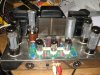
It sounds much better, particularly the bass. I played Santana's Supernatural, and the bass and drums go down low and growl in a way that I've not heard from this amp before.
IMG_0435.JPG
 
Back
Top Bottom