• The move to the new server is done. There are some software and database maintenance updates in process. This has us passing the hat around to help out. We appreciate any donations. Seriously, even a dollar helps. The payment page may be found here - https://www.audiokarma.org/support.html

Biasing a Model 1200

ocdecio

The proof of the restoring is in the listening.
Subscriber
To what extent the 240/250 procedure of biasing by checking the voltage across R531/R532 at 12-15mv applies to a 1200? The 250 has a higher rail voltage (58V vs 52V) given that it is 125WPC whereas the 1200 is 100WPC.

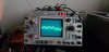
The reason I ask is that it seems like setting it to 12-15mv distorts the signal quite a bit (the bottom of the wave wiggles). As soon as I begin raising the bias, the wave goes back to normal.

If anyone biased a 1200 - what method / voltage did you use?
 
Register to hide this ad
@rBuckner I am totally confused. So I took what you mentioned - "check for crossover distortion at 20kHz. Enough bias and there shouldn't be" to be my measure. Nothing else. I went from full CCW with a wave, it had the classic distortion in the middle of the wave indicating lack of bias, and as soon it disappeared I stopped. Bias voltage? 0.2mv. I continued to go up in amplitude with the signal gen, no (visible) distortion.

I turned it off, connected a DAC and a speaker. Played some music. Sounded as good as any of my other amps. 0.2mv bias. If that's what it takes, I'm good with it.

Or is there danger lurking under the surface that I am not seeing?
 
Did you then try other frequencies like 10kHz, 1kHz, 100Hz and 20Hz? Also run the volume control up and down, no speakers of course! That's an awfully low bias and the danger would be that it would go into full oscillation I would think.

I just did my first Model 19 and had one amp do the clipping and wobbling thing at the level equivalent to 5 watts. Someone had replaced the original outputs and TO-66 transistor on the heatsink using MJ1500X and TIPxxx parts but did both channels. So I was thinking I had a leaky transistor on the driver board but could find nothing using a DCA tester and later an "octopus" tool I got capable of a 24 volt swing. Preventatively I changed 3 pre driver TO-39's and still had the issue. There are two pots for + and - "load limit" that I started tweaking back and forth and could eliminate the clipping on top an bottom up to the point where it otherwise hit the rail. I'm not at the computer that has the manuals but are there similar pots in the 1200? I know I didn't need to tweak any such thing in the 1200 I did but they may have been there!
 
I tried all frequencies, but up to 120mv input to be fair. Clean wave. If I raise the bias all hell breaks loose. It does have the "load limit" pots so I should be able to tweak these.

I'll slowly run the volume above that and see how far I can get. Hope no plums of smoke!
 
@rBuckner since you mentioned the load limit pods, I decided to take a closer look at Q506 and Q507 which are part and parcel of the limiter circuit. Originally they are 2N4125 and 2N4123, which are usually replaced with 2N3906/2N3904 - which I dutifully installed since the whole channel had blown out.

Hey this amp wasn't taking any of it. I managed to source the originals 2N4125 and 2N4123, gold leads and all. Guess what. That seems to have made a difference. There may be other issues related to distortion since I still need to review the relay board and the power supply.

20210423_165241.jpg

Fingers crossed... I'm leaving it on for a bit. Hey I really appreciate the insights!
 
Last edited:
Well great! Honestly and at the risk of exposing that I'm an idiot sometimes, I was thinking out loud as I was typing. I had a manager once say in jest (I think!) that I just knew enough to be dangerous! :D

There were a couple of transistors on the Model 19 amp driver board that had the 2N3904 as a recommended replacement which is what I used. I had a stash from a place I worked at from 1980-1987! Some had the gold plated leads so naturally I used them for the bling factor!!
 
Check out the max power output adjustment info in the SM on page 14, it is what I had to tweak to "fix" the 19 I was working on. It is the adjustment of the positive and negative peak clipping using pots R541 and R542.
 
Check out the max power output adjustment info in the SM on page 14, it is what I had to tweak to "fix" the 19 I was working on. It is the adjustment of the positive and negative peak clipping using pots R541 and R542.
I am gathering courage to max it out :) I have a 100W / 8Ohm dummy load that may not be able to handle it. But I will have to git'it'done!

As for the bling factor - I got a bunch of 2N4250 glob tops with golden leads that are used everywhere in pieces of this vintage.
 
Well great! Honestly and at the risk of exposing that I'm an idiot sometimes, I was thinking out loud as I was typing. I had a manager once say in jest (I think!) that I just knew enough to be dangerous! :D

There were a couple of transistors on the Model 19 amp driver board that had the 2N3904 as a recommended replacement which is what I used. I had a stash from a place I worked at from 1980-1987! Some had the gold plated leads so naturally I used them for the bling factor!!
I have no problems admitting ignorance and I appreciate being set straight. As for electronics, I am basically an "idiot with a degree" LOL
 
I would do it without the load at first, then the bravery part can be applied! Nice grab on the 4250's.
Oh thank you for the tip! That way there won't be much risk of overwhelming the board/outputs and I still can see where the clipping starts.
 
Back
Top Bottom