• The move to the new server is done. There are some software and database maintenance updates in process. This has us passing the hat around to help out. We appreciate any donations. Seriously, even a dollar helps. The payment page may be found here - https://www.audiokarma.org/support.html

BIASING PROBLEM ON A 6V6 PP TUBE AMPLIFIER WITH HIGH VOLTAGE ON THE KATHODE ,P8

FILIMENTHEAD

New Member
i have an ELECTROHOME PA 310 mono pp. amp . for some reason that i cannot resolve is that i get high voltage of 373 volts dc on pin 8 of the 6v6 outputs where there should only be 18 volts .
both 6v6 tbes are connect on pin 8 with a biasing potentiometer between the 2 tubes with a 470 ohm resistor connected to p8 of each tube .
i keep getting a 373 dc voltage reading and thus toasting the 20 uf -100 volt capacitor attached to p8 . for biasing .
i dismantled and re assembled 3 times , replaced resistors , capacitors and double checked and also i have the schematic and all connections check out correct .
CAN ANYONE SHED SOME LIGHT ON THIS OR HAVE A SUGGESTION ? i also replaced the 6v6 and all of them tested good on my tester .
A HAIR PULLING EXPERIENCE .
PLATE VOLTAGE SUPPOSED TO BE 308 VOLTS , BUT I GET 425 VOLTS AT THE 5Y3 ,P8 AND 375 ON THE PLATES OF THE 6V6 . so how can high voltage of 373 volts end up on the kathodes . the power transformer has 320v x 2 centre tapped and its the original .
 
Last edited:
Register to hide this ad
Welcome to AK!

This is the introductions thread where you introduce yourself and hopefully tell us a bit about you.

Technical questions such as yours above belong in the correct sub-forum - such as:-

This one

You can request that the thread/post be moved by reporting your own post using the 'Report' link below left in your post.
 
Last edited:
Thread moved to "Tube Audio", , , , 'cause it sure isn't any kind of introduction.

FILIMENTHEAD, going forward, please be mindful of which area of AK you post your threads to. Not scolding, merely educating, that here we have a place for everything, and appreciate having everything in it's place ;)
 
i have an ELECTROHOME PA 310 mono pp. amp . for some reason that i cannot resolve is that i get high voltage of 373 volts dc on pin 8 of the 6v6 outputs where there should only be 18 volts .
both 6v6 tbes are connect on pin 8 with a biasing potentiometer between the 2 tubes with a 470 ohm resistor connected to p8 of each tube .
i keep getting a 373 dc voltage reading and thus toasting the 20 uf -100 volt capacitor attached to p8 . for biasing .
i dismantled and re assembled 3 times , replaced resistors , capacitors and double checked and also i have the schematic and all connections check out correct .
CAN ANYONE SHED SOME LIGHT ON THIS OR HAVE A SUGGESTION ? i also replaced the 6v6 and all of them tested good on my tester .
A HAIR PULLING EXPERIENCE .
PLATE VOLTAGE SUPPOSED TO BE 308 VOLTS , BUT I GET 425 VOLTS AT THE 5Y3 ,P8 AND 375 ON THE PLATES OF THE 6V6 . so how can high voltage of 373 volts end up on the kathodes . the power transformer has 320v x 2 centre tapped and its the original .
post the schematic so people can help out with the circuit
 
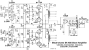
Here's the output stage of the schematic I found online. It says "Electrohome PA-310."

Ehome PA-310.jpg

Jack
 
6aq5 and 6v6 are pretty interchangeable other than the obvious socket differences, and the 6aq5 is rated for a bit lower voltage and dissipation for physical size reasons. Wouldn't be very surprising if the early version was a 6v6 and got changed to a 6aq5 in later production.
 
both 6v6 tbes are connect on pin 8 with a biasing potentiometer between the 2 tubes with a 470 ohm resistor connected to p8 of each tube
Sounds as though the pot might be open. That would result in a high voltage at the cathodes, and B+ would go up the way you described because the output tubes aren't drawing any current.

One more thing - the schematic I found doesn't show a line fuse in either the schematic or the sketch of the chassis. If yours is like that, I suggest adding a fuse holder before continuing.

Jack
 
So, the schematics don't show a pot in the cathode circuit.
This could be your problem.
You're output stage uses pentodes with a 10 watt disapation, times 2.
So there's roughly 20 watts being disapated in your output stage which the cathode resistor must be sized to pass.
That's why it's a bigger unit than a 1/2w unit of the same value.
In order to adjust bias current or even it out so that the tubes are conducting evenly, it's common to see a pot which varies the grid voltage, in order to bias the tubes.
Rarely is this done via a pot in the cathode circuit.
The reason for this is simply cost.
The cost of a huge hi wattage variable resistor to adjust bias via the cathode would be prohibitively expensive. A pot to vary the grid voltage is cheap by comparison.

Since there's no pot in the schematic and you say there's one there, and there's a good chance it's open, I'd hook the non grounded end of the 330ohm cathode resistor directly to the cathode pins and see what you get.
Remove the pot entirely from the cathode circuit of the output stage.
Test it on the bench.

If you or someone else pulled the full output stage current through a half watts pot, then that pot can be assuned to be toast, and most likely failed open which lets the tube conduct fully but leaving the b+ with no place to go after the cathode.
So it sits on the cathode waiting for a path to ground.
 
Last edited:
The way it's described by the OP, the two 470Ω would be bias resistors, and the pot would be DC balance. Just an educated guess of course without seeing the exact schematic. Is the OP still around? :)
 
Back
Top Bottom