• The move to the new server is done. There are some software and database maintenance updates in process. This has us passing the hat around to help out. We appreciate any donations. Seriously, even a dollar helps. The payment page may be found here - https://www.audiokarma.org/support.html

BIC 1000 need Help

tazman3276

Active Member
I have a BIC 1000 Turntable. I’m having a problem with the platter motor. It spins slowly and studders. It wants to spin freely but doesn’t. I’m wondering if it’s an adjustment problem. I would appreciate any help that I can get.
Thank you
 
Register to hide this ad
I have of those.

Have you cleaned all the old grease off the main bearing and applied new?
 
The motor itself is easily removed and disassembled. Clean out the old lube and add new.

I doubt it’s bad; there’s not much that can go wrong with them.
 
The motor itself is easily removed and disassembled. Clean out the old lube and add new.

I doubt it’s bad; there’s not much that can go wrong with them.
Thank you for your thought on this. I did take apart the motor and put on new lube. Is there anything else that I can try to fix this problem?
 
Does it spin freely mechanically - ie with no power and belt off (and not in cycle...)?
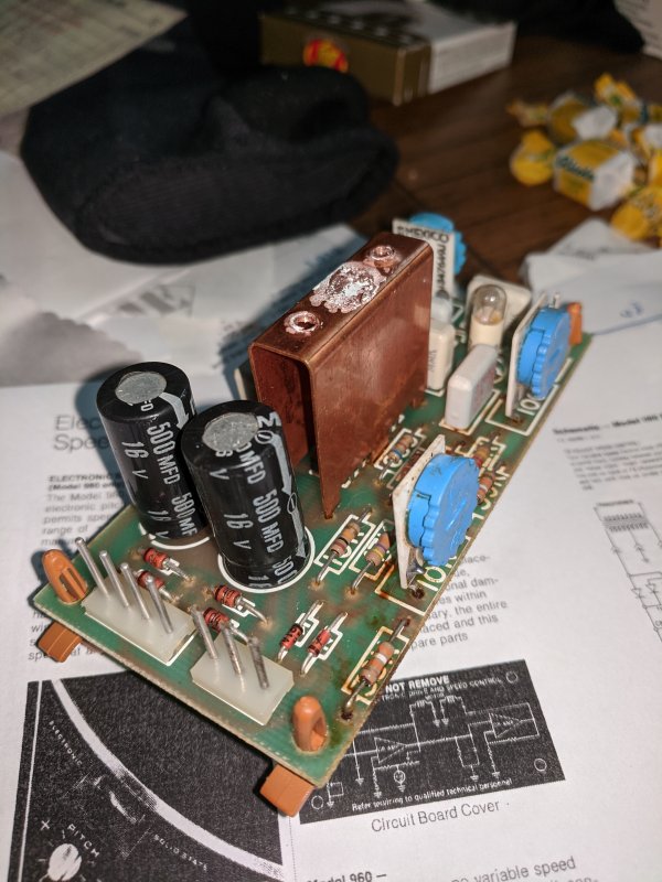
The 1000 and 980 use the same oscillator board to drive the motor - try searching for the adjustments as they could be off three pots which can cause this problem.
Also somebody (I think) had similar problem solved by recapping the boards, but this isn't a likely cure.
 
Does it spin freely mechanically - ie with no power and belt off (and not in cycle...)?
The 1000 and 980 use the same oscillator board to drive the motor - try searching for the adjustments as they could be off three pots which can cause this problem.
Also somebody (I think) had similar problem solved by recapping the boards, but this isn't a likely cure.
Yes it does spin freely. I’m hoping that it’s something simple. I don’t know anything about recapping the board. What are the 2 Blue pot that are on the board? Is that where I can make adjustments to the motor?
 
Yes it does spin freely. I’m hoping that it’s something simple. I don’t know anything about recapping the board. What are the 2 Blue pot that are on the board? Is that where I can make adjustments to the motor?
I have a question. I disconnected the remote control cord from the board. Would this cause it to have this problem?
 
I am posting a compilation of the posts I made in another thread on how to adjust the motor control board:

The motor control board is the same for the 980, 981, and 1000.

Anyway, the pot on the end of the board is for adjusting the platter speed so the strobe is stationary when the pitch
control on top is in the center of its travel. First set the pitch control to its center and then turn the pot on the
board so the strobe is stopped.

But first! - Go to the Vinyl Engine/Library/BIC/Service Information section and find the number 8 service bulletin for
980s That bulletin deals with adjusting the oscillator although it's not really complete. The front pot closest to the
bulb is for adjusting the AC voltage to the motor. The other front pot, farthest away from the other two, is kind of a
balance pot and, even though I am no circuit design expert and don't have my schematics handy, I believe it adjusts the
oscillator outputs so they are in phase.

Normally, you would use an Oscilloscope to adjust this but I have always just set it so the bulb on the board is lit
fairly dimly and steadily. That means the voltage passing through it is at a steady state and indicates an in-phase
condition. This adjustment can be a bit tricky.

The order in which the adjustments are made: First set the AC voltage to the motor (from service bulletin #8). Second,
adjust the other front pot to get the little bulb on the board to burn dimly and steadily - no variation in brightness at
all, no pulsing. Third, set the pitch control on top to its center and adjust the pot on the end of the board so the
strobe is still. That's it.

Start by setting all controls (3) about mid range. Adjust the pot on the long side of the board, closest to the bulb, for
the 4 or 5 volts across each motor coil as described in the service bulletin. Is the platter rotating the correct
direction? If so, adjust the other pot on the long side of the board so the bulb lights dimly and steadily. Not real
dimmly but not bright either. It should never pulse, regardless of how long you watch it. This may take some getting used to, recognizing when the pot
is in the correct range and when it is adjusted for the correct position for the correct brightness AND absolutely NO
pulsing. You will discover this.

If the platter doesn't rotate or rotates the wrong direction, turn the other pot on the long side of the board until the
platter DOES rotate the correct direction and proceed as above. Lastly, turn the pitch control (on top of the base plate) until it is mid range (don't worry about the strobe marks yet).Then turn the pot on the control board, on the end of the board, until the strobe marks on the side of the platter, stand
still.

Done

If you look at the schematic, you can see the pot by the bulb (100 ohm) is in the feedback loop on the first op amp and
so, directly adjusts the AC voltage level.

The other pot (10 k ohm) zeros out the quiescent voltage with DC voltage in the loop. When adjusted correctly, the
crossover for the AC voltage will be 0 volts which is why the bulb doesn't pulse.

 
Last edited:
I am posting a compilation of the posts I made in another thread on how to adjust the motor control board:

The motor control board is the same for the 980, 981, and 1000.

Anyway, the pot on the end of the board is for adjusting the platter speed so the strobe is stationary when the pitch
control on top is in the center of its travel. First set the pitch control to its center and then turn the pot on the
board so the strobe is stopped.

But first! - Go to the Vinyl Engine/Library/BIC/Service Information section and find the number 8 service bulletin for
980s That bulletin deals with adjusting the oscillator although it's not really complete. The front pot closest to the
bulb is for adjusting the AC voltage to the motor. The other front pot, farthest away from the other two, is kind of a
balance pot and, even though I am no circuit design expert and don't have my schematics handy, I believe it adjusts the
oscillator outputs so they are in phase.

Normally, you would use an Oscilloscope to adjust this but I have always just set it so the bulb on the board is lit
fairly dimly and steadily. That means the voltage passing through it is at a steady state and indicates an in-phase
condition. This adjustment can be a bit tricky.

The order in which the adjustments are made: First set the AC voltage to the motor (from service bulletin #8). Second,
adjust the other front pot to get the little bulb on the board to burn dimly and steadily - no variation in brightness at
all, no pulsing. Third, set the pitch control on top to its center and adjust the pot on the end of the board so the
strobe is still. That's it.

Start by setting all controls (3) about mid range. Adjust the pot on the long side of the board, closest to the bulb, for
the 4 or 5 volts across each motor coil as described in the service bulletin. Is the platter rotating the correct
direction? If so, adjust the other pot on the long side of the board so the bulb lights dimly and steadily. Not real
dimmly but not bright either. It should never pulse, regardless of how long you watch it. This may take some getting used to, recognizing when the pot
is in the correct range and when it is adjusted for the correct position for the correct brightness AND absolutely NO
pulsing. You will discover this.

If the platter doesn't rotate or rotates the wrong direction, turn the other pot on the long side of the board until the
platter DOES rotate the correct direction and proceed as above. Lastly, turn the pitch control (on top of the base plate) until it is mid range (don't worry about the strobe marks yet).Then turn the pot on the control board, on the end of the board, until the strobe marks on the side of the platter, stand
still.

Done

If you look at the schematic, you can see the pot by the bulb (100 ohm) is in the feedback loop on the first op amp and
so, directly adjusts the AC voltage level.

The other pot (10 k ohm) zeros out the quiescent voltage with DC voltage in the loop. When adjusted correctly, the
crossover for the AC voltage will be 0 volts which is why the bulb doesn't pulse.
Doug
I’ve been trying to adjust the pots but can’t get it right. Is there anyway that if I send you the motor control board you can adjust it? I can’t seem to keep the bulb to stay on. I tried to cycle it but once it goes to the next spot the bulb goes off. What am I doing wrong?
 
Hi Michael,

Although I could take the board and mount it into a table to adjust, and that's the only way to do it, It wouldn't necessarily be correct for a different table. The adjustment for the bulb is very touchy. BIC should really have used a multi-turn pot to do that. Of course, if an oscilloscope were available to do it, that would make it much easier because you can see the sine waves involved and adjust the circuit based on those instead of watching the bulb.

The problem is, as soon as you think you're in the right spot for the bulb to be dim and not pulsing, you have gone past the correct spot. You just have to go very slow and turn the pot in very small increments.

Doug
 
Hi Doug and all, I am not sure if you are still on this chat ... I followed bulletin #8 faithfully but the voltage between pin 4 & 6 can only go from 6.18 - 6.3 volt. And it's 0.01 volt between pin 5 & 7. Pin 4&5 tied together as ground, I think ... since my motor has a red and black leads, I should get something around 4 volts. Does that mean my circuit board is a goner?
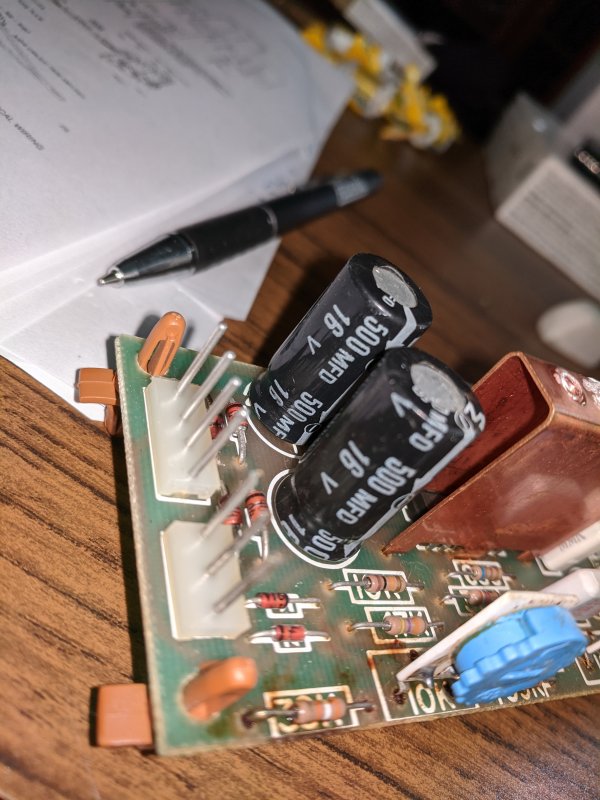
I am thinking of replacing the caps 500uF/16v next. Should I start looking for the IC?
I spent 3 hours to clean and relube, get it to run about 30 minutes then the motor stuck. With power off, I can turn the motor easily but when I power one, look like the circuit has a magnetic field that lock the motor. I think somehow the circuit stuck in a phase the lock down the motor.

the light can be changed and dim but never flickering ...

Please help. My BIC 980 is almost new!!!

Thank you,
 
Well, it sounds like the board is bad but unplug the motor and try to adjust the voltages. If still bad, it's the board. Do the pots seem OK? Not rough or anything?

Adam at Turntable Experts sells the IC's on eBay. And yes, check the caps and replace if necessary.

Doug
 
Well, it sounds like the board is bad but unplug the motor and try to adjust the voltages. If still bad, it's the board. Do the pots seem OK? Not rough or anything?

Adam at Turntable Experts sells the IC's on eBay. And yes, check the caps and replace if necessary.

Doug
Pots look good and turning smoothly. My electrolytics caps are 500uF however... Thanks. I will try again without the motor connection... and will report back. The IC code is M642 377
 
Well, it sounds like the board is bad but unplug the motor and try to adjust the voltages. If still bad, it's the board. Do the pots seem OK? Not rough or anything?

Adam at Turntable Experts sells the IC's on eBay. And yes, check the caps and replace if necessary.

Doug
Hi Doug,

I unplugged the motor, the voltage now is between 10.8 - 11.3 volts.
Will replace the caps next, then call upon Adam ...

Thanks,
 
I replaced the caps. The old one labeled as 500uF measured at 670 uF. I replaced both with 460uF/50volts. The voltages between pin 4 & 6 does not change, still around 10.8 volts without motor connection. When connected they are at about 5.7 volts but the specs calls for 4 volts.

Also, it looks like the feedback loop is not working. I can only dim the bulb using the pot next to it, the one on the 2 power pins does not change the brightness of the bulb at all. Am I right that the feedback loop does not work? The light is always solid, only the brightness changed when I turn the pot next to it ...

I guess I now have to call Adam... Hope fully it's the IC. code is 377. Are you familiar with it?

Thanks,
 
Last edited:
The 10 volts with the circuit open is probably normal as the motor coils, which are actually part of the circuit, are not in circuit then. The pot right by the bulb, of course, is to adjust the two voltages to the motor coils. I guess I have never really noticed what turning it does with the bulb. The other pot on the long side of the board (down by the connectors) should make the bulb pulse AND make its brightness change.

The bulb always being at a steady brightness indicates one of the oscillators isn't working and, if all other parts, traces, etc. are good, the IC is the prime suspect as that IS the two oscillators (with the external components) to run the motor. Although I have never had a bad IC nor had to replace one, if everything else is OK, it must be that.

The 377 is a dual amplifier chip made into Wien bridge oscillators with external components. The resulting AC voltages power the motor coils and thus, cause it to run. The board adjustments are to get the outputs to the correct voltage for the motor and get the two oscillators in phase. The third pot, on the narrow end of the board, is just a rough adjustment for the motor to run at the correct speed when the control on top is set to its center position.

Doug
 
Doug, thank you for your kindness and clear explanation of the circuits and its function. My guess is that since the bulb is not flickering. It indicates that the IC/Oscillators are not working. But again, IC rarely fails. After replacing the caps, the voltage seems to go down somewhat but not at the specs they have specified in the Bulletin #8 (mine is a red/black cables to the motor). Have you seen the 2 caps valued at 500uF? someone else mentioned that those are 1000uF. Would that double the voltage in my circuit? to my knowledge, caps is to hold the amps, not volts ... !!! I really want to get this BIC980 to work since I already have problems with my Duals :-) ... BIC seems to be mechanically simpler but now I face this state of the art brushless motor issue :-) Again, thanks for your help. I am waiting for an email from Adam ...
 
The capacitor values aren't that critical. They just filter the DC supply voltage and your original were probably fine.

The problem IS with the oscillators and any one component in either oscillator being bad will stop the oscillation and thus, the motor. Of course, you want to be sure all the components and the board, itself, are OK but if they are, trying another LN377 is the next logical step. Although ICs are normally very reliable, it's possible it got overheated and failed.

Doug
 
Back
Top Bottom