• The move to the new server is done. There are some software and database maintenance updates in process. This has us passing the hat around to help out. We appreciate any donations. Seriously, even a dollar helps. The payment page may be found here - https://www.audiokarma.org/support.html

Bogen CHB 35a - Guitar Amp Conversion - I have questions (of course)!

ryanpg

New Member
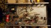
I got a Bogen CHB 35a. A 6C4 phase inverter is on the way from Triode USA. The OT and 7868 tubes are working.

I'm reading the schematic (attached) and I'm a bit baffled on a few points. To start with, the OT. So many secondary windings! I'm not too concerned about the 24v but I'd still like to eliminate the terminal; I'd like to "eliminate" the 70v sockets; what's up with "REM 1" and "REM 2?" Do I understand correctly that there's nearly 240v AC on those two screws? If I'm right, then that's nuts. I'd definitely like to eliminate those two terminals, but of course without screwing up the plate voltage of the 6EU7.

So a basic question about the OT. Can I simply cut and shrink tube the 70v grey, and separately cut and shrink tube the 25v blk/red wires? (Or will leaving these two windings open cause issues with kickback and impedance on the tube side of the OT?)

Basic question about plate voltage. Can I eliminate the wires going from the junction of the 470K and 330K to the screw terminals? Or should I just replace the three series resistors on the plate supply (470K, 470K and 330K) with a 1M plate resistor in series from the 240v output of the PT? (I suspect I'm wrong in thinking I need to add the values of the resistors.)

Thanks! I have more questions!
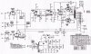
bogen-chb35a-6small.jpg
 
Last edited:
Register to hide this ad
You can just tape off the BLK/RED (25V) and GREY (70V) output taps.

High voltage is present on the remote control terminals, but it's current-limited (<1mA). You need to keep the pair of 0.22uF caps in place to avoid changing gain. If you want to simplify the circuit, just tie the two 6EU7 anode resistors to a single cap of at least 0.47uF (to ground), and route a single 390K resistor from there to the +240VDC supply tap.
 
Personally, I would just leave all output connections alone as stock. Because it is a PA amplifier, the 25 & 70 volt is used for impedance matching transformers which are used for long run speakers in schools, malls, auditoriums etc. When there is nothing connected to them, there is no need for worry that something or someone is going to get shocked. I own a Bogen PA amp with the same output taps and am currently just using the 8Ω tap but all others are left alone and intact.

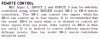
The REM 1 & 2 (mine has a 3) are for a remote volume control preamp. The pic is from a Bogen model M120 manual but the same also applies for yours.
BOGEN M-120 INPUT CONNECTIONS 3.jpg


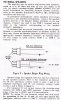
This is for the M120 but might also be helpful in your situation.
BOGEN M-120 SPEAKER CONNECTIONS.jpg
BOGEN M-120 SPEAKER CONNECTIONS 2.jpg
 
Last edited:
I've converted a couple tube PA amps to guitar amps (changing/adding gain stages, implementing different tone stacks, asymetrical diode clipping, master volume to output stage, etc., etc.) and always left all the output taps as they were. Simply connected speaker to the most applicable one.

Far as the HV outs, I'd probably do somethine about those, probably just cut or desolder the leads at the terminals and heat shrink the ends. This I would do for now, until you get a feel if you're going to use it mainly stock or do more mods.
 
I might unhook the two REM connections and seal them off just to keep the HV off exposed terminals. The rest you can just leave alone. Lots of taps on PA trafos is pretty normal, its for the distributed speaker systems as mentioned.
 
I've actually converted one, but don't currently have access to any pictures to share. I'm pretty sure that I isolated the 70v / 25v taps, and removed them from the terminal strip. You can also remove the REM1 REM2 from the terminals, but the power supply is wired directly to the screw terminals, and resisters (2x 470K) then to a terminal strip with the two .22 uf caps. Still tweaking mine / playing around with a basic preamp tremolo circuit.
It sounds pretty good for what it is.
 
OK, since this will never again be used as a PA, I've decided I'm going to remove as much as possible (including extraneous inputs and volume controls). Re: REM1 and REM2, I'll have to trace the wires to the junction at the terminals and rebuild from there. I'm taping off both the 25v and 70v.

I'm planning on doing a single Fender style input, 68K in series, 1M pull-down. (Eventually I'd like to rewire that stage for a 12ax7.)

Is there any benefit to rewiring the 6EU7 to be in series rather than parallel?

But more simple questions:

Can I use ONE 1M pull down if I tie grids V1A and V1B together? I think yes, or use a single 2M.
Do I need to keep the ceramic caps (.1/100) in place? I'm planning to omit.
I want to omit the AUX 1 and 2 inputs and INPUT 2 VOLUME along with AUX VOLUME and MIC 1 VOLUME circuits. Do I just connect both plate outs of the 6EU7 after the coupling caps?

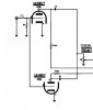
Does the below work?

bogen-chb35a-input.jpg
 
Last edited:
Oh, and then the other thing that jumped out at me: cathode bypass capacitors. Wouldn't it make sense to add them to the 6EU7 and possibly the 12ax7?
 
cathode is grounded on the 6EU7, so no need to bypass it. Adding them to the 12ax7 would increase the gain, which it probably doesn't really need. TRy it stock first, adjust as needed later.

Personally I wouldn't parallel the tube like that. If you're going to do it, tie both plates together directly and use a single coupling cap and plate resistor at half the value of the original, or 220k is close enough to half original.

If you ran it in series it would probably have waaay too much gain.
 
The two sections of the 6EU7 are for separate microphone inputs - why not keep them?. Don't eliminate the coupling cap, will affect 6EU7 bias. The "grid leak" bias (no cathode resistor) is usually not used for guitar, as it has poor overload characteristics. But some like it for harmonica. Cathode resistors on the 12AX7 are so low that bypassing them won't have much effect. And bypassing the second 12AX7 stage will short the negative feedback. (possible you WANT that in a guitar amp...). The tone controls may work for you, though some will change to Fender or Marshall circuit (more gain, maybe better suited to the particular guitar and pickups).
 
If you ran it in series it would probably have waaay too much gain.

Possibly. If you just wire them straight up with the "book" values probably.

However, if you have interstage level contols then it makes for lots of interesting tone & character possibilities.
 
Last edited:
IMG_3635.JPG
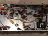
This is where Mine currently stands.
Looks like I removed rem1 &2, removed both mic vol controls, and the input fader. I was playing with a single
Tube tremolo circuit, so my 6eu7 is completely reworked and the first two pots are speed / intensity. I haven't teally had time to change anything else.


You could check out http://el34world.com/charts/TubeAmpSchematics.htm for some ideas.
Good Luck!
 
As well, AX84 dot com has lots of plans too. I converted the front end of a Grommes S35 to the preamp/tone stack used in the AX84 Single Ended Lead (SEL) design. Three gain stages with a cathode follower driving the tone stack, then a master volume before the 6C4 phase splitter and P-P 7868 output stage.

Overall, the Bogen and Grommes look very similar in design, but Grommes used two 6EU7 instead of 6EU7 and 12AX7.
 
Thanks all! I love AX84 and el34world, both excellent resources. I'll be browsing through the schematics, designs, and theory until the 6C4 arrives. I want to start my modifications on a platform that I know is working. Going to post some pics of the amp as-is soon.
 
bogen-chb35a-mods.jpg

So, I completely eliminated the 6EU7 for now. I'm just starting to sketch in a 12ax7 gain stage in its place. The amp is playing great, a little quiet for some reason, but getting decent breakup with everything on 10. : )

Above I'm wiring in a 1/4" speaker jack. On the + side, there's now a wire that goes outside the chassis that can be attached to the screw terminal at whatever impedance you want.

Next elementary question:

The 12ax7 Cathode has a strange configuration to me. There are grid resistors (680 an 470k) but there's also a 240v supply with a 220k resistor in series connected to the cathode. What's that about?

Also, the negative feedback loop is really odd. It goes from the 16ohm speaker tap, through a 33k resistor (I can't find the cap that's supposed to be there), back to the 260v supply. What's the deal there? Is this a "reference to B+ is the same as reference to ground" design? Doesn't this provide high voltage to the 16ohm terminal?

Thanks!
 
Also, the negative feedback loop is really odd. It goes from the 16ohm speaker tap, through a 33k resistor (I can't find the cap that's supposed to be there), back to the 260v supply. What's the deal there? Is this a "reference to B+ is the same as reference to ground" design? Doesn't this provide high voltage to the 16ohm terminal?

Thanks!

That's the negative feedback. It is supposed to go where it does. You will also notice that besides going through the 33K resistor, it also goes to the cathode of the 12AX7 tube and then ground via a 470Ω resistor. You do not get high voltage to the 16Ω tap or you would have some unpleasant goings on.

If you can, locate an H.H.Scott 222 or LK72 or such amplifier and have a look at their feedback designs.
 
Last edited:
That's the negative feedback. It is supposed to go where it does. You will also notice that it does go to the cathode of the 12AX7 tube and then ground via a resistor (can't make out the ohms). You do not get high voltage to the 16Ω tap or you would have some unpleasant goings on.

Thank you for your reply, and for confirming my understanding. I'm familiar with NFBs, it's the cathode voltage that's confusing me.

What's the purpose of the voltage on the cathode? And why (thankfully) isn't there high voltage on the 16ohm terminal?
 
What's the purpose of the voltage on the cathode? And why (thankfully) isn't there high voltage on the 16ohm terminal?

Someone else might be able to explain it better than I but I think the 220K resistor acts like a shunt but not sure. I have seen that configuration before in other amps but I do know that you are not getting high voltage on that 16Ω winding unless it is some sort of unusual feedback design associated with that Bogen amp & design. I'll have to study my Bogen amp schematic and see how they did it. Never thought about it as it works fine the way they designed it.
 
Last edited:
Biasing the tube with a voltage divider lets you use a smaller cathode resistor (increasing gain) and eliminate the bypass cap. Resistor costs less than a cap, and small electrolytics are less reliable.
 
Back
Top Bottom