• The move to the new server is done. There are some software and database maintenance updates in process. This has us passing the hat around to help out. We appreciate any donations. Seriously, even a dollar helps. The payment page may be found here - https://www.audiokarma.org/support.html

Bogen E75 - anyone ever seen/heard/worked on one of these?

nickdinatale

Active Member
I recently got one of these from a lighting and sound company that was cleaning out their warehouse. Allegedly, it was used in the old Boston Garden for PA purposes. I did a Bogen DB20DF a few years ago and was really impressed with the sound, so I'm eager to see what this one can do. This amp seems to be a very similar unit to the DB20, just with two amps in one chassis, meant for PA, and a number of years earlier (no 9-pin mini tubes in this one).

It looks as though it'll be a very easy conversion to stereo. The old owner modded it to employ 3 channels of microphone inputs and no phono input. I'm torn as to whether I should mod it to have 2 channels of phono input, or whether I should just forget about that area and go with inputs straight to the power section. I figure getting a good phono sound out of it may be a little more difficult.

Pics coming in a few.
 
Register to hide this ad
Roll of solder and cutters included in the first photo for scale. At some point, something went south in channel one (the big, multisection wirewound is burnt)
 

Attachments

  • IMG_0800.JPG
    IMG_0800.JPG
    116 KB · Views: 124
  • IMG_0799.JPG
    IMG_0799.JPG
    101.2 KB · Views: 131
  • IMG_0798.JPG
    IMG_0798.JPG
    96.1 KB · Views: 123
Twin mono amp, pretty bitchin. Two of everything. Push-pull 6L6 with a driver transformer, so probably AB2 operation. I have the SAMS for it if you need it, but it says it will run 70w paralleled so I'd assume 35 wpc.

phono would be crystal cartridge anyway, you'd need an RIAA stage to make that work unless you modified the mic amps to do that. I think you might be able to get away with that.
 
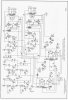
bah, scanned it at the wrong setting and the file is too big. Shoot me a PM with your email and I can send it that way. Its about 10mb. In the meantime here's the schematic, if it doesn't resize too small

Bogen E75 schematic.jpg
 
Heavy beast, 60+lbs. Dual mono PS, nice! Reminds me of the Stromberg-Carlson AU-35 but dual PS & interstage Xformer coupled output, so possibly similar application. Schematic available in this related thread also but looks like gadget has even higher res version. Also available from Radiomuseum for download. 1950s PA system, possibly not wide frequency response needed for that app but will be interesting to see your findings.
 
Heavy beast, 60+lbs. Dual mono PS, nice! Reminds me of the Stromberg-Carlson AU-35 but dual PS & interstage Xformer coupled output, so possibly similar application. Schematic available in this related thread also but looks like gadget has even higher res version. Also available from Radiomuseum for download. 1950s PA system, possibly not wide frequency response needed for that app but will be interesting to see your findings.
Definitely heavy! Yeah, I'm very interested to see how it performs once I restore it, even just as a power amp. I've never heard anything with an interstage transformer in it, so at the very least it'll be a learning curve. This blog post sounds promising.
 
The transformer does phase inversion duty, but I also suspect it might be providing grid current ability too. Grid current gets into the land of significant power output, probably the only way its possible to get 35 watts from a 6L6G. A 6F6 is actually a power output tube, though not an especially stout one. Triode-wired like it is the datasheets give not quite 1 watt of power output. Should be plenty enough as a driver though.
 
Same. I really hope the bias rectifier warms up faster than the B+. I might consider swapping that for a solid state just to be absolutely sure.
 
Right now I'm in the process of getting it rebuilt back to the factory schematic (thank you, gadget!) just to make sure it functions properly. Not overly complicated aside from the time consuming part of replacing the can caps. A good quarantine project though!
 
Update! Spent the majority of the past day or two working on this thing. I've bypassed the microphone preamp and preamp sections and am going straight from RCA jacks into the grids of the second 6SL7 (V4) (also bypassing the volume control pots). I'm wondering - how would I determine the grid stop value to use? Also, I'm assuming I'll want some sort of input cap? This is the first time I've ever made adjustments like this to an amp, so I'm learning as I go. The good news is, it passes signal pretty well. I ran a few songs worth of John Prine through it before powering it back down this evening.
 
grid to ground at V4, 470k is fine. If you need a grid stop in series, ideally square wave testing to see if its got overshoot problems that need taming would be of help. Failing that, try maybe 10k. The bigger it is, the more HF roll-off you'll get.

Cap between input jack and the grid stop isn't a bad idea but if your preamp doesn't chug out DC its not absolutely neccesary. 0.1uf into 470k will be fine though.
 
Thank you, Gadget. Testing it today with just the grid to ground. I'm thinking that the bias rectifier is warming up slower than the B+ as you had mentioned previously. Starting it straight from the on/off switch results in a growing hum - I'm assuming this is a result of that happening? When I start slowly from a variac, all is well.
 
if the bias voltage comes up slower than the output tubes conduct, the output stage is going to try and move a bunch of current until the grid supply comes up. You wouldn't hear it immediately, but you might hear the transformer growling after a couple seconds then shut up as the current drops back off. A 5X4 is direct heat, so it will warm pretty quick. The 7Z4 is indirect so it will come up slower. The 6L6 are also indirect but its probably a coin toss which gets going faster. Likely pretty close to the same warmup time.

if you want to see if thats whats going on, you could just connect a silicon diode in place of the 7z4. That would give you full negative bias immediately. Prob need a resistor to get the voltage right though, I'd expect it to be too negative with a diode.
 
@nickdinatale Any updates on your project? There's one of these on the auction site now, and cheap too, I'm eyeing it and curious if you ever discovered how it sounds.
 
I'm also curious. Had forgotten all about this. I have too many projects to justify yet another but I'd be content if someone else figured it out and let us know.

**edit** if someone here already bought it, thank you for making sure I don't have to feel guilty about buying yet another thing I don't need
 
@gadget73 It wasn't me, but I had the exact same thought! At that price with free shipping it was really tempting me, glad someone else put an end to that.
 
Back
Top Bottom