• The move to the new server is done. There are some software and database maintenance updates in process. This has us passing the hat around to help out. We appreciate any donations. Seriously, even a dollar helps. The payment page may be found here - https://www.audiokarma.org/support.html

Bogen voltage problems.

Carbsandcaps

Super Member
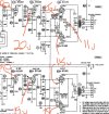
Bear with me this may be a long one. Working in a bogen srb-20 with some strange biasing and voltages. It uses 6BM8 outputs. Pin 9 (the plate of the triode) has 90v instead of 120v. Pin 1 (the grid of the triode) has 20v on it.

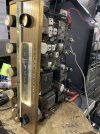
The biasing has a weird setup. I’m supposed to have 20v on the cathode of the outputs but I can only get 15v. This circuit also feeds the preamp heater which I’m only getting 11v to. The circuit then goes back to the hum balance pots. I anlso found that the resistor to ground anfter the cathodes was 470ohm instead of 4700ohns so I replaced that. I’m assuming it gets the 20v from the voltage through the tubes? It sounds good and all the B+ voltages are good but I don’t like the low voltage on the triode plate and 20v on the grid. IMG_3038.jpegIMG_3039.jpegIMG_3040.jpeg
 
Register to hide this ad
I'm in the middle of something else at this moment, so not enough time for a complete analysis. However, I can tell you that the negative voltage on the grids of the triodes is the result of grid leak bias. It can't be measured with a meter.

Jack
 
I'm in the middle of something else at this moment, so not enough time for a complete analysis. However, I can tell you that the negative voltage on the grids of the triodes is the result of grid leak bias. It can't be measured with a meter.

Jack
This is positive voltage. It’s almost like it’s drawing voltage away from the plate since the plate voltage is 40v low.

This is affecting both channels.
 
No chance that should be negative or even zero. Look at where the 1M resistor ties. Its 120k above ground. The cathode is marked as 40v over 125600 ohms
Not going to do the math but (40 / 125600) * 120000 will tell you what it is. Expect about 38 volts though. Easier to measure this at the junction of all 3 resistors. At the grid you have to consider meter loading is skewing this. Confirm the 1M isn't open too, though the value isn't overly critical.


if the plate and screen voltages are about right and the cathode voltage is low, the tubes are probably tired. Confirm the screen voltage though, it has a very large effect on this.
 
No chance that should be negative or even zero. Look at where the 1M resistor ties. Its 120k above ground. The cathode is marked as 40v over 125600 ohms
Not going to do the math but (40 / 125600) * 120000 will tell you what it is. Expect about 38 volts though. Easier to measure this at the junction of all 3 resistors. At the grid you have to consider meter loading is skewing this. Confirm the 1M isn't open too, though the value isn't overly critical.


if the plate and screen voltages are about right and the cathode voltage is low, the tubes are probably tired. Confirm the screen voltage though, it has a very large effect on this.

The resistors all measured close to spec. I have almost exactly 40v at the cathode. The tubes are a possibility. I have 2 new Russian 6BM8’s and 2 used ge 6bm8’s for testing. All 4 tubes measured good on the tester but all 4 showed very high grid emissions. I’m not sure if this is a fluke of the tester though since they all measure that way.
 
Bet the -1.5V is measured grid to cathode.
That's why I asked about the black square notation. I do think the 1M resistor is developing a degree of grid leak bias, but it may not be enough to matter much. In fact, the only voltages of importance for troubleshooting that stage are the anode and cathode. If those are close, it's working.

Jack
 
oh, another thought on the output stage, did you adjust the balance pots for minimum hum? The way this one does things it actually affects current flow through one of the tubes in the pair and if its too far off it will end up making the cathode voltage lower than it ought to be.

Pretty dumb way of doing it honestly, it only allows you to add more resistance to the cathode of one of the two tubes. If the tube drawing more current isn't in V10 or V13 the adjustment won't actually null the hum out correctly. Normally there is a little bit of feedback to the output tube grids, or the wipe goes out to the main cathode resistor and the ends go to the tubes so it will increase current on one tube as it drops the current on the other.
 
Ok so grid to cathode measure -2.1vdc so you guys were right on that one. I would still like to figure out why the output cathode voltage is low.
 
oh, another thought on the output stage, did you adjust the balance pots for minimum hum? The way this one does things it actually affects current flow through one of the tubes in the pair and if its too far off it will end up making the cathode voltage lower than it ought to be.

Pretty dumb way of doing it honestly, it only allows you to add more resistance to the cathode of one of the two tubes. If the tube drawing more current isn't in V10 or V13 the adjustment won't actually null the hum out correctly. Normally there is a little bit of feedback to the output tube grids, or the wipe goes out to the main cathode resistor and the ends go to the tubes so it will increase current on one tube as it drops the current on the other.

I have messed with the hum pots but they don’t seem to affect the cathode voltage much if at all. I thought the 4700ohm resistor is what would change that but I could be wrong.
 
I would still like to figure out why the output cathode voltage is low.
This voltage could vary considerably from unit to unit. It's dependent on the exact resistance of the filaments being powered by the DC current from the cathodes, and It will also change as the output tubes age. I wouldn't worry about any of this as long as power supply voltages are reasonably close and both channels make good power.

Jack
 
I have messed with the hum pots but they don’t seem to affect the cathode voltage much if at all. I thought the 4700ohm resistor is what would change that but I could be wrong.

cathode voltage on the output tubes. Those bias with one 12ax7 heater in series with a 22 ohm resistor. If the balance pots (not the hum pots) are set correctly it should have a null in the hum on each channel when you get it right. Might be easier to hear this with headphones, or honestly i tend to use a scope for this since its fairly clear on the display where it hits minimum hum.

if you find its at it's best with the adjustment all the way one direction on a channel, reverse the two tubes in that channel and see if it won't let you balance it out without the pot all the way at the end.
 
Well I had it playing for a while today and it sounded great. I did mess with the hum adjustment but I didn’t hear much difference when moving it. It was more of a change of tone than volume but I don’t see much point in messing with it until I get my output tubes that I’m going to be using. Then I’ll use a scope to set it.

I guess now my only concern with the biasing is that the preamp 12ax7 is running at 11.5v on the heater instead of 12. I’m wondering if when it’s all said and done with the new outputs if I can change the 22 ohm resistor to get 12v at the preamp tube. IMG_3065.jpeg
 
11.5v on a 12ax7 is fine. A lot of them were run under-volted for noise reasons.
The old Akai reel decks powered the 6.3V filament of the EF86 head amp with 5.7V. It says so right on the power transformer, and this filament winding even has its own hum pot.
 
Back
Top Bottom