• The move to the new server is done. There are some software and database maintenance updates in process. This has us passing the hat around to help out. We appreciate any donations. Seriously, even a dollar helps. The payment page may be found here - https://www.audiokarma.org/support.html

Bose 1801 Monster Power Amp Restoration!

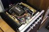
Today's project was to install the new main caps, and the DC protection circuitry.

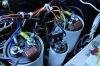
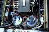
The main caps were 14000uf, now they are 22000uf. They are rifa/kemet caps. Very good load life, low esr, etc. They were smaller diameter, so I had to install new clamps. The smaller cap has a bolt coming out of the bottom, so I drilled a hole and bolted it down instead of using a clamp.

Check out the improved ground I made, the 7 strand 15 gauge per strand copper pillar connected to the chassis between the new main caps. Three strands go to each main cap, one to the secondary cap.

The 4 diodes on top of the secondary cap was replaced with a 1 part diode bridge.

The DC circuitry boards were from analogmetric. They are powered from a small 19VAC transformer I mounted under the main rectifier. I had to change a resistor on the analogmetric boards because the voltage on pin 4 of the IC, for power on detection, was higher than the datasheet for the IC recommended, and because my supply voltage was a bit higher than recommended.
 

Attachments

  • 1801balls-0.jpg
    1801balls-0.jpg
    80.4 KB · Views: 144
  • 1801balls-1.jpg
    1801balls-1.jpg
    90.6 KB · Views: 166
  • 1801balls2-0.jpg
    1801balls2-0.jpg
    107.5 KB · Views: 148
  • 1801balls2-1.jpg
    1801balls2-1.jpg
    64.7 KB · Views: 144
Last edited:
Almost there!

Wow! It looks great!

Thanks so much for taking on this project Racoon1400!

I can't wait to hear it all integrated into my system! This is going to be awesome! :tresbon: :banana::banana::banana:
 
The smaller cap has a bolt coming out of the bottom, so I drilled a hole and bolted it down instead of using a clamp.

Just a caution---make sure the bolt is not sitting below ground potential. I believe the bolt on the PEH200 caps is connected to the negative terminal. When that terminal is ground it is OK, but if that terminal has a negative voltage (like when it is filtering the negative rail) the bolt won't be at ground potential (and you'd want to insulate it from the chassis).

Steve
 
This was a cool thread!. I picked it up late. You guys are brilliant. Trying to absorb the wisdom for the future. Thanks all. Congrats on getting the beast up and running!
 
Just a caution---make sure the bolt is not sitting below ground potential. I believe the bolt on the PEH200 caps is connected to the negative terminal. When that terminal is ground it is OK, but if that terminal has a negative voltage (like when it is filtering the negative rail) the bolt won't be at ground potential (and you'd want to insulate it from the chassis).

Steve

You're right, the bolt IS connected to the negative terminal. Fortunately, the negative terminal is grounded anyway. Makes for a nice solid ground connection.
 
Last edited:
Wrote about my 1801. Repaired By: John at "Fine-Tuned audio video.com" In Orlando Florida. Pickup 8/23/2013. Bias extremely was high replace transistor Q4 and Diode CR7.
 
Last edited:
I did a bench test for watts with this thing. One channel gave me a nice clean sine wave up to 338Watts into 8ohm, exceeding the rating of 250W. (and both the top and bottom clip at the same time)

But the other channel starts to clip the top of the sinewave at 40W. The offset rises to a few hundred mV. What could cause this?

Both driver boards have new caps, metal film resistors in place of the carbon comps, new transistors, new zeners, and new outputs. But the to-66 drivers are original.
Offset and bias are in check at idle.

Interestingly, this is not the same channel I was having issues with before.
 
Last edited:
I have a 1801 with power to the rear power outlet when switch is on. But do not have lights or sound. Looking for repair shop. Jacksonville, Fl. Or will ship to repair shop. Anyone know who do repairs. Very very clean amplifier. Will post pic. Thanks.
I know someone on the west Florida coast, near Tampa, if you're willing to take a drive.
 
I did a bench test for watts with this thing. One channel gave me a nice clean sine wave up to 338Watts into 8ohm, exceeding the rating of 250W. (and both the top and bottom clip at the same time)

But the other channel starts to clip the top of the sinewave at 40W. The offset rises to a few hundred mV. What could cause this?

Both driver boards have new caps, metal film resistors in place of the carbon comps, new transistors, new zeners, and new outputs. But the to-66 drivers are original.
Offset and bias are in check at idle.

Interestingly, this is not the same channel I was having issues with before.

First check the supply voltages, especially on the positive rail for the outputs and drivers. Next, check that channel's output with no load. If it looks ok, then voltage amplification is ok and the problem is with current drive on the positive side. Possibly bad driver transistor.
 
First check the supply voltages, especially on the positive rail for the outputs and drivers. Next, check that channel's output with no load. If it looks ok, then voltage amplification is ok and the problem is with current drive on the positive side. Possibly bad driver transistor.


The supply voltage is fine. Positive supply starts at 88V. When I drive the good channel to clipping, it gets dragged down to 82V. The bad channel starts clipping the top of the wave at 85V. If I turn up the good channel, the bad channel starts clipping slightly sooner.

With no load, there is still an issue. But I get a bit more AC voltage at the output before it does. 25 as opposed to 18VAC.

Outputs are new, but the drivers are not.
 
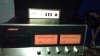
:music:Raccoon1400 try contacting John (Fine-Tune audio.com) He repaired my 1801 in 3 days including 50 hrs of continuous run time. Had burned R7. Bad power supply bridge rectifier D1-4. Bias extremely high unable to adjust down . Replaced Q4 transistor and diode CR7. Amp working great.
 

Attachments

  • IMAG0916.jpg
    IMAG0916.jpg
    35.3 KB · Views: 49
  • IMAG0909.jpg
    IMAG0909.jpg
    57.2 KB · Views: 38
Last edited:
The supply voltage is fine. Positive supply starts at 88V. When I drive the good channel to clipping, it gets dragged down to 82V. The bad channel starts clipping the top of the wave at 85V. If I turn up the good channel, the bad channel starts clipping slightly sooner.

With no load, there is still an issue. But I get a bit more AC voltage at the output before it does. 25 as opposed to 18VAC.

Outputs are new, but the drivers are not.

With no load, turn it up until it clips on the bad channel. Then start probing the bases of the transistors on the positive side, from the outputs toward the front end until you find the stage that is clipping on the top. Note that PNP transistors will have the base driven negative so you look for clipping on the bottom there.
Wrap the tip of the probe with electrical tape so only the very tip is exposed to avoid shorting things out if you slip. You probably have a bad transistor or maybe an open resistor.
 
I tracked the issue back with the scope and found the issue appeared to be the op-amp. I then noticed the +16V supply was 4V. I pulled the op-amp, and the voltage went back to normal. So it would appear the issue is the op-amp.

This opamp was originally in the channel I was having problems with, then I swapped them channel to channel.
 
Last edited:
I tracked the issue back with the scope and found the issue appeared to be the op-amp. I then noticed the +16V supply was 4V. I pulled the op-amp, and the voltage went back to normal. So it would appear the issue is the op-amp.

This opamp was originally in the channel I was having problems with, then I swapped them channel to channel.

Good job!:thmbsp:
 
So ordered a "NOS" part off ebay, form ukraine. Put it in, and no relay click. On closer inspection, offset was +15V. On even closer inspection, the supplies for the opamp were off. But not the same way as before. The + side was fine, the -ve side was only a couple volts. So bad new part? Before it was the +ive side that had issues. Pulled the part and supplies are back to normal.

I'm thinking the next step is to try the OPA604 Thierry used?
 
Back
Top Bottom