• The move to the new server is done. There are some software and database maintenance updates in process. This has us passing the hat around to help out. We appreciate any donations. Seriously, even a dollar helps. The payment page may be found here - https://www.audiokarma.org/support.html

Bose 901 EQ capacitors

whoaru99

Epic Member
Probably been asked before, but....

Attached is schematic of 901 Series II EQ. Going to replace the 13 electrolytic caps (all others are film or ceramic) and wondering if any positions are necessary to try to more precisely replicate the listed values rather than the standard values typically available today?

I underlined the electrolytic cap positions for one channel (did not underline the common PS caps). Which would be considered audio path caps possibly for something like Silmic or Nichicon FG or KZ "audio capacitors"?
 

Attachments

Register to hide this ad
FWIW, ordered Sprague Atoms for the 500uf filters, Vishay BCs for the 100uf caps, and Elna Silmic IIs for the output coupling caps.
 
Last edited:
All electrolytics are on order and will be replaced, but unlikely I will shotgun the whole board unless some other performance issue is noted. Presently, the only hard fault is the left channel output coupling cap (C53) is totally kaput.

When that's all sorted will evaluate the response of both channels and if any further action seems necessary (the obligatory Deoxit treatment already completed).
 
Last edited:
Two of those are audio coupling, the rest are all bypass or decoupling caps to ground None are part of the EQ or anything like that. I think you'd be fine with nearest available modern values. C11 and C13 appear to be the only audio coupling caps, so if you wanted a better quality part, thats where I'd put it.
 
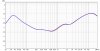
Here's a sweep on the left and right channels of the Series VI eq.

Both channels track pretty close, within ~0.5dB across the board. That's the type of thing I'll try with the Series II eq when the left channel is fixed by the recapping.

Right = Red
Blue = Left

901SerVI_BothCh.jpg
 
looks perfectly reasonable given component tolerances. Probably wasn't any tighter when it rolled out of the factory.
 
Math based on the graph and a manual test using frequency generator and voltmeter, both align and confirm the Series VI eq is within Bose specifications for the frequency response curve.
 
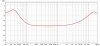
Here's the functional channel (right) of the Series II eq.

The 20Hz frequency test point is -3dB out of spec, all other test points are within the Series II specifications. Perhaps the new cap in the coupling position will address the 20Hz point. Will know later in the week, perhaps as early as tomorrow evening.

901SerII_Rch.jpg
 
Last edited:
All electrolytics are on order and will be replaced, but unlikely I will shotgun the whole board unless some other performance issue is noted. Presently, the only hard fault is the left channel output coupling cap (C53) is totally kaput.

When that's all sorted will evaluate the response of both channels and if any further action seems necessary (the obligatory Deoxit treatment already completed).

Everything I've ever read regarding those EQs, and my own personal experience, says that the resistors and other passive components are all either junk or worn out and need to be replaced. YMMV.
 
Everything I've ever read regarding those EQs, and my own personal experience, says that the resistors and other passive components are all either junk or worn out and need to be replaced. YMMV.

I appreciate that, but the measurements of these suggest no need for shotgun reconditioning. The Series VI EQ is in spec as it sits, and Series II appears to need only minor work to bring it into spec (although all electros will be replaced in that one). Of course, like anything, some units may be worse off than others/YMMV.
 
Last edited:
In the Series II it looks like there are a lot of carbon comp; most, maybe all, I reckon.

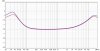
I scrounged up a 4.7uF cap from my stash of bits and replaced the Left channel C53 coupling cap. That channel now passes signal. Based on preliminary results looks like L channel has 3-4dB more output at 20Hz than the R channel, which would make the L channel within spec across the board and even more centered within the spec at the upper end.

Red = Right ch (original/untouched)
Blue = Left ch (new C53 coupling cap)

The intended new caps for both channels are now showing not due until Friday (sticks out bottom lip, LOL).

901SerII_R_Lch.jpg
 
Last edited:
I appreciate that, but the measurements of these suggest no need for shotgun reconditioning. The Series VI EQ is in spec as it sits, and Series II appears to need only minor work to bring it into spec (although all electros will be replaced in that one). Of course, like anything, some units may be worse off than others/YMMV.

If they aren't carbon comp resistors, fair bet they haven't drifted much.

It's not so much "in spec," as somehow Bose managed to get their hands on some really, really lousy quality components that both sound bad and do some really crazy stuff like pick up stray FM signals (I recapped but did not fully rebuild a Series III/IV EQ that did this). As noted, though, YMMV, and I don't know much about the parts past the Series IV.
 
It's not so much "in spec," as somehow Bose managed to get their hands on some really, really lousy quality components that both sound bad and do some really crazy stuff like pick up stray FM signals (I recapped but did not fully rebuild a Series III/IV EQ that did this). As noted, though, YMMV, and I don't know much about the parts past the Series IV.

Well, not sure what you mean by lousy parts.... looks pretty much like plain old resistors and capacitors to me and, frankly, cleaner construction and better soldering than I've seen in a lot of other stereo gear.

To some degree I'm picking the common hate on Bose vibe. If that's not it, OK, sorry, but sorta gettin' that...
 
Well, not sure what you mean by lousy parts.... looks pretty much like plain old resistors and capacitors to me and, frankly, cleaner construction and better soldering than I've seen in a lot of other stereo gear.

To some degree I'm picking the common hate on Bose vibe. If that's not it, OK, sorry, but sorta gettin' that...

Ugh. I'm trying to give you advice based on experience. I don't know what the deal with the components was, or if they simply used lower wattage parts than they should have, but there are a number of people who reported surprising results after completely rebuilding the EQs.

If you think I'm a Bose hater, you should see the twin stacks of four 901 Series IIIs sitting in my basement awaiting refoam and refurbishment.

https://audiokarma.org/forums/index.php?threads/bose-901-equalizer-built-from-scratch.631535/
http://www.dhsspeakerservice.com/News-or-Reviews.html
 
The Series II eq is recapped (electros only) and both channels are now handily within Bose's frequency response spec. Up to 10kHz both channels basically overlay each other, above 10kHz exhibits deviation between channels similarly, but now less (~0.6dB) than you see in the graph of post #14.

Going to start on the speakers themselves next. The first test on them from the Bose service manual is to apply 25Vrms @ 10Hz to check for buzzes or rattles. That should be interesting. Hopefully not too much for the old gals.
 
Last edited:
1. Rub and Tick Test

1.1 Apply a 10 Hz, 25 Volts rms signal
(with the use of an amplifier) to the speaker
terminals. Refer to Figure 8. No extraneous
noises such as rubbing, scraping, or ticking
should be heard.


2. Sweep Test

2.1 Apply a 25 Volt signal, and slowly
sweep the oscillator from 10 Hz to 75 Hz.
There should be no loud extraneous
noises. If there are any loud buzzes or
distortion, replace any defective driver.

2.2 Reduce the amplifier output to 10 Volts
and continue sweeping the signal from 75
Hz to 15 kHz. Listen for any buzzes, rattles,
and other extraneous noises. Dress any
wires that might be the cause of the noise.


3. Phase Test

3.1 Using a 6 to 12 Volt dc supply.
Connect the positive (+) wire to the positive
terminal and the negative (-) wire to the
negative terminal on the speaker. Check
that all drives are in phase, all drivers
should move outward. If one or more
drivers move inward the wiring should be
checked. Refer to Figure 4
 
Finally got around to doing the speaker tests. They passed but there was quite the cacophony as sweeping though the frequencies, particularly the mid bass though mid range, made all sorts of stuff in the room rattle or buzz, LOL.

I'd advise earplugs too.
 
Back
Top Bottom