• The move to the new server is done. There are some software and database maintenance updates in process. This has us passing the hat around to help out. We appreciate any donations. Seriously, even a dollar helps. The payment page may be found here - https://www.audiokarma.org/support.html

Boston Acoustics a100 - various versions & crossovers

sba2

New Member
Crossovers

It appears that the A100 evolved during its 1980's production life. The original model (series 1) had the woofer midway between the top and bottom. The later models (series 2 and 3) had the woofer nearer to the top and nearer to the tweeter; the later enclosure was also 2" taller than the earlier series 1.

The above changes, as well as the new tweeter that was introduced in the series 2, probably led to the crossover design changes.

I just picked up a pair of the A100, series 2. The crossovers have two inductors (1.65 & .50 mh) , two capacitors ( 6 & 16 uf) and one resister for the tweeter ( 2 ohm).

An earlier crossover had both a different number of components & and different component values.

With my pair of A100s, although one of the 16uf capacitors had migrated to 20uf due to age (and both inductors were of low quality) the sound captivated me enough to rebuild the crossovers using better air coil inductors that I had laying around, and some Audyn Q4 capacitors that I purchased from parts express.

The crossover upgrade resulted in modestly better sounding speakers. But I should point out that larger air coil inductors, and film caps, are much more expensive than the original crossover parts. And the project could easily require a good days work, depending on your setup and experience.

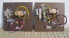
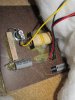
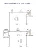
Here are some images of A100 crossovers (from the internet) and a schematic I drew of the A100, series II crossover--

* * * * * * * * * * * * * * * * *


The original A100s (series 1), with the round SEAS tweeters, crossed over at 1600 hz :
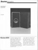
series 1 - 1600hz.jpg

series 1 - 1600hz (1).jpg

A100 early crossover.jpg

A100 early crossover C.jpg

a100 early crossover d.jpg


* * * * * * * * * * * * * * * * *


The series 2, with the rectangular Boston made tweeters, crossed over at 2000 hz :
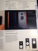
a100 specs.jpg


* * * * * * * * * * * * * * * * *

This is a later, series 2 or 3, crossover :
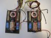
A100 early crossover B.jpg


* * * * * * * * * * * * * * * * *


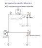
My series 2 crossover contained only a single resistor. Here is the schematic I drew :
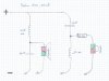
Boston A100 series II.jpg

(the woofer is 4 ohm nominal, and the the tweeter 6 ohm nominal)
 
Last edited:
Register to hide this ad
Here is an early set of A-100s with the SEAS tweeters that I picked up at an estate sale/auction recently, along with a very dusty $10 Yamaha receiver. (After a clean-up and deoxit treatment, the Yamaha plays and sounds really nice.) Also included is a pic of the crossovers. The label on the woofers indicate 1982 manufacture.

After a refoam, they sounded good. I suspected they could be better, so I installed Solen caps and Mills resistors (original specs = 16uF and 1.5ohm). Did one speaker and compared the two side by side - big improvement to my ears... higher extension, more smooth/even response, less "harsh", etc (no scientific measurements, just listening tests). The total cost of the speakers, new correct foam surrounds, and crossover parts was around $65. If they cost twice as much, I would still be happy with the price/performance ratio - very enjoyable speakers. I would describe them as typical east-coast; smooth, laid back, non-fatiguing. After some experimenting, I have them placed flat against the wall - lifted off the carpet with small blocks of wood.
 

Attachments

  • auction.jpg
    auction.jpg
    58.1 KB · Views: 304
  • crossover.jpg
    crossover.jpg
    63.3 KB · Views: 283
Last edited:
You got off easy my friend, my A200's crossovers have about five times as many components jammed into a tight space. They were designed specifically to be placed against the wall so there's no surprise that's where they ended up. Great job on rescuing and restoring some classic speakers.:beerchug:
 
Tweeters

The original A100s (series 1) used several Seas tweeters:

H 211
H 241 L
H 253 (with ferrofluid)

A100 early tweeter.jpg

* * * * * * * * * * * * * * * * *

Seas H 241 L
BA - seas 241L.jpg


* * * * * * * * * * * * * * * * *
Seas H 253
BA - seas h253.jpg

The H 253 spec sheet is attached below. Interestingly, Seas recommended crossing the tweeter more than an octave higher than what BA actually had done.

* * * * * * * * * * * * * * * * *

The Seas tweeters were eventually replaced in the early 1980s with a newer model that came off Boston Acoustics well-regarded production line. The Boston tweeters had a rectangular mounting plate, and they appeared with the A100, series 2. They were continued with the series 3.
 

Attachments

Last edited:
Measurements

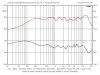
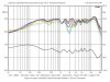
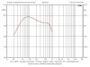
Zilch measured the A100s several years ago. Here are his measurements and his comments:


A100 On Axis.jpg


A100 VP Map.jpg


A100 NF Bass.jpg


Zilch's comments:

1) Except for the peak @ ~13 kHz, it's flat within +/- 1.5 dB in the axial response. The peak likely itself flattens off-axis horizontally, where we typically listen if they're not toed in. The HF rolls off above there, so there's not very much "air."

2) Bass response is typical for large acoustic suspension designs like ARs and Advents, extending down to 30 Hz at -6 dB. A100 is certainly not lacking in this department.

3) The vertical polar map is symmetrical about the tweeter axis, and well behaved within +/- 10 degrees from there, somewhat cleaner (-) than (+).

4) Phase is well aligned.

5) They got it "right...." :yes:
 
Last edited:
Need a little help with caps on this one
I have a pair of series 1s. Got the foam from Rick Cobb and pulled the woofers only to discover that
they are actually Taiwanese pioneer knock offs. Foams have to go back. The crossover has been updated but I am not sure
if they are the correct caps. Anyone with values? These Frankensteins have become a bit of a battle but I like the cabs and grills.
Next...If I use one of the Dayton replacements that are supposedly perfect for these, do I keep the caps at stock value. Any help appreciated.
 
Very interesting, the woofer inductor looks exactly like the one in the OLA.

It would be great to know the DCR s of the different series woofers.
 
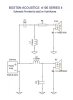
Here is a schematic for the A-100 Rev1 based on the picture in the thread
linked below and a guess at the inductor value. I had trouble reading the values
off of the picture in the OP but the resistor value looks different, 1.5R vs. 3R
might be due to different models of the SEAS tweeter:
http://www.audiokarma.org/forums/in...oustics-a100s-possibly-need-recapping.131618/

I assume that the yellow tweeter wire goes to the positive tweeter connection
and drew it as such with the drivers in phase:
The crossover picture in post #2 of this thread has the tweeter in phase and a 16uF feeding it so slightly
different than shown in this schematic.
BA-A100-REV1.jpg

The tweeter is driven hard with a 20 uF cap, and the woofer is driven full range
connected directly to the input terminals. This is similar to the New Large Advent
in the Increase position where the woofer inductor is shorted. There will be very
little baffle step and I expect these to be forward sounding. I can see a lot of "Advent"
in these speakers.
 
Last edited:
Here is the Series II schematic, I confirmed the same values for Rs and Cs from an ebay picture. This is the OPs schematic:
The tweeter is wired out of phase and in the crossover schematic the yellow tweeter wire (+) goes to
the negative input terminal.
BA-A100-REV2.jpg
 
Last edited:
This is the 2 resistor version shown in a picture by the OP, not sure if it is an update
to the Series II crossover or the Series 3 version. I like this one best with
more attenuation on the tweeter and some damping on the woofer cap to
reduce peaking before the final LP rolloff:
BA-A100-REV3.jpg
 
Here is a schematic for the A-100 Rev1 based on the picture in the thread:
http://www.audiokarma.org/forums/in...oustics-a100s-possibly-need-recapping.131618/

...I assume that the yellow tweeter wire goes to the positive tweeter connection
and drew it as such with the drivers in phase:
View attachment 1393958

Sorry I'm a little late to the party, but the tweeter should be wired in apparent opposite phase to the woofer (per the other referenced schematics above) which then puts it in actually correct phase because the 2nd order crossover inverts its polarity 180 degrees.
 
Sorry I'm a little late to the party, but the tweeter should be wired in apparent opposite phase to the woofer (per the other referenced schematics above) which then puts it in actually correct phase because the 2nd order crossover inverts its polarity 180 degrees.

That is the standard text book theory, however, 2nd order electrical filters combined
with the acoustical response of the drivers (even it not perfect or exact) result in some
sort of 4th order electro-acoustical response where often the drivers are wired in phase.
It all depends and you will find both ways in practice.

Look at the Minimus 7 mod on here that is based on my design, 2nd order filters and the
drivers are wired in phase.
 
So in a nice early set of A100's I am restoring currently they have crossovers the same as the OP showed in the first crossover picture above. Similar to those above, they are slightly different from one another. Why? Is there a reason? One of them sends the positive through the protection fuse before the caps and resistor while the other after those components.
 
Wasn't sure weather I should create a new thread or add to this one. Let me know if I should move this. I have a nice pair of BA A100 Series I speakers that I am going to rebuild. I am a bit of a BA groupie going back to the early 80s so the project is more out of nostalgia and love for the speakers than anything else. I don't mind investing my time and a little money. I am also learning this as a hobby and plan to keep them in my collection of vintage speakers. Value of parts and effort vs value of speakers is not a huge consideration. I have a few questions and would like some thoughts on my plans. I am going to start by building a removable crossover that will be securable to the floor of the speaker, add banana plug binding posts instead of screw terminals and eventually add a real wood walnut veneer instead of the vinyl wrap. The dogs lunch glued to the back of the speaker although functional, has to go!!

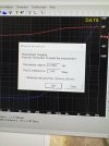
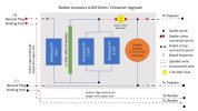
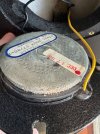
I want to thank people who have previously contributed to the cross over discussion. Super helpful!! Attached is a pic of the crossover in my speakers. 1-20uF Cap, 1-8uF cap, 1-1.5ohm resistor and an air core inductor that measures at 0.75mH (ave between two speakers) and 1.77 ohms dc resistance with a Dayton DATs v3. Do these values seem right (pic attached)? I have looked at new coils and they seem to have much much lower resistance values. Parts Express has three air coil inductors rated at 0.75mH that all have dc resistance specs of between 0.3 and 0.46 ohms. Why so high on the ones in my A100s? My plan is to use metalized PP caps. Any preferences on Dayton, Solen, Jentzen, Clarity? I can find the 20s from a few manufacturers. I cant find a straight up 8 only 8.2 so I will wire two caps in parallel to give the correct value. Does this make sense or should I just use the 8.2? I have attached a schematic of my cross over plan for comment. Its based on what was shared previously for a series I A100 just with parallel wire of two caps to replace the single 8uF cap. Let me know if I have it right.

I did not understand the comments about wiring the tweeter out of phase. The tweeter in my speakers has the yellow wire attached to what is identified as the positive (red) post on the speaker. So, I am assuming they are wired in phase. Maybe the phase discussion was for series II speakers?
 

Attachments

  • Inductor measurement.jpg
    Inductor measurement.jpg
    63.2 KB · Views: 18
  • Crossover Upgrades A100(3) copy.jpg
    Crossover Upgrades A100(3) copy.jpg
    68.4 KB · Views: 18
  • A100 Seas tweeter.jpg
    A100 Seas tweeter.jpg
    87.9 KB · Views: 19
  • Existing A100 crossover .jpg
    Existing A100 crossover .jpg
    73.8 KB · Views: 18
Wasn't sure weather I should create a new thread or add to this one. Let me know if I should move this. I have a nice pair of BA A100 Series I speakers that I am going to rebuild. I am a bit of a BA groupie going back to the early 80s so the project is more out of nostalgia and love for the speakers than anything else. I don't mind investing my time and a little money. I am also learning this as a hobby and plan to keep them in my collection of vintage speakers. Value of parts and effort vs value of speakers is not a huge consideration. I have a few questions and would like some thoughts on my plans. I am going to start by building a removable crossover that will be securable to the floor of the speaker, add banana plug binding posts instead of screw terminals and eventually add a real wood walnut veneer instead of the vinyl wrap. The dogs lunch glued to the back of the speaker although functional, has to go!!

I want to thank people who have previously contributed to the cross over discussion. Super helpful!! Attached is a pic of the crossover in my speakers. 1-20uF Cap, 1-8uF cap, 1-1.5ohm resistor and an air core inductor that measures at 0.75mH (ave between two speakers) and 1.77 ohms dc resistance with a Dayton DATs v3. Do these values seem right (pic attached)? I have looked at new coils and they seem to have much much lower resistance values. Parts Express has three air coil inductors rated at 0.75mH that all have dc resistance specs of between 0.3 and 0.46 ohms. Why so high on the ones in my A100s? My plan is to use metalized PP caps. Any preferences on Dayton, Solen, Jentzen, Clarity? I can find the 20s from a few manufacturers. I cant find a straight up 8 only 8.2 so I will wire two caps in parallel to give the correct value. Does this make sense or should I just use the 8.2? I have attached a schematic of my cross over plan for comment. Its based on what was shared previously for a series I A100 just with parallel wire of two caps to replace the single 8uF cap. Let me know if I have it right.

I did not understand the comments about wiring the tweeter out of phase. The tweeter in my speakers has the yellow wire attached to what is identified as the positive (red) post on the speaker. So, I am assuming they are wired in phase. Maybe the phase discussion was for series II speakers?

How did you get along with building your new crossovers ?

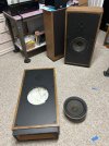
I just replaced the foam surrounds on a pair of A-100's and listening to them now. First impressions are very good. I think I'll use them a while before deciding on re-capping the crossovers. The large cabinets make the ten-inch woofers appear small. The tags on the mid-woofers were dated May 20 1982.


Boston A-100 #1.jpg


Last edited:
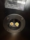
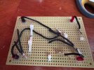
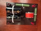
Nice! These must be series II. Mine are series I and don't have a built in base. I just got my parts last week. I held off building the crossover because I started over thinking the impact of adding resistance from the additional lengths of wire that would result from moving the crossover board off the terminals. I found a reference that put me at ease. The resistance for 1000 ft of 14ga oxygen free copper wire is ~2.6 Ohms so adding a few feet of total length inside the cabinet to connect everything up will not have a an impact on sound (In theory). Any changes I hear should come from the upgraded parts. As an experiment I tested all of this with a pair of BA A70's. Banana plugs, 14ga OFC wire and an off terminal crossover with Clarity Pure Caps (2 X 12uF wired in series for 6uF final). The transparency of vocals and acoustic instruments went off the charts to my ears. I love the way they sound. I previously did a swirled cheery veneer on these and they are now complete!! I'll be working on the A100s this coming week.
 

Attachments

  • A70 Banana Plugs.jpg
    A70 Banana Plugs.jpg
    62.2 KB · Views: 21
  • A70 Crossover Back.jpg
    A70 Crossover Back.jpg
    135.8 KB · Views: 22
  • A70 Crossover.jpg
    A70 Crossover.jpg
    78.6 KB · Views: 27
  • A70 Cherry Veneer.jpg
    A70 Cherry Veneer.jpg
    53.5 KB · Views: 27
Thanks for the reply. I don't know much about electronics, but your cabinets are beautiful ! I hope you will continue to post updates.
 
Your A100's are the original series, not Series II. The tweeter is correctly wired as you describe it; it is in phase with the woofer. The base was an optional accessory on the Series I. On the Series II it came factory installed. The base raises the speaker and improves its looks in my opinion, and I regret not having made it a standard item on the Series 1. As for the inductor, don't replace it. The inductance and the resistance of that inductor were chosen specifically to provide the best sound. As for the 8 uF capacitor, an 8.2 cap is an excellent replacement.

If you have any other questions, please let me know.
 
Your A100's are the original series, not Series II. The tweeter is correctly wired as you describe it; it is in phase with the woofer. The base was an optional accessory on the Series I. On the Series II it came factory installed. The base raises the speaker and improves its looks in my opinion, and I regret not having made it a standard item on the Series 1. As for the inductor, don't replace it. The inductance and the resistance of that inductor were chosen specifically to provide the best sound. As for the 8 uF capacitor, an 8.2 cap is an excellent replacement.

If you have any other questions, please let me know.
I don't know why AK says I am a new member. I have replied on AK before, mostly on KLH speakers, where I worked back in the 1960's. I designed all of the Boston Acoustics A series speakers. Andy Kotsatos
 
Back
Top Bottom