• The move to the new server is done. There are some software and database maintenance updates in process. This has us passing the hat around to help out. We appreciate any donations. Seriously, even a dollar helps. The payment page may be found here - https://www.audiokarma.org/support.html

Boston Acoustics A70 elusive crossover schematic

Stuart Pedaso

In too deep
Subscriber
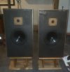
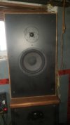
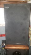
Pulled out my A70s to rotate into service for a bit and began mulling the technical aspects of these fine speakers. Not well versed in BA lore, I turned to the vast knowledge of the Web for enlightenment and am perplexed to discover no crossover schematic anywhere to be found. Seems odd for a very popular speaker enjoying ample buzz in the audio forums.

So it became a WTH moment, prompting me to pop one open and have a look. I have series I A70's, though with the Boston tweeter rather than earlier SEAS tweeter. The crossover in these is mounted on the terminal cup (unlike series II apparently). Mine look like this ...

A70_CR.jpg

... with an air-core coil mounted on the reverse side:
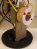
A70_L.jpg

The coil is not labeled so I lifted some leads to measure it and the other components while already in there.
AND I traced out the schematic; to post here so I can find it next time I go looking.
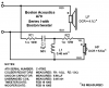
BA-A70_schematic.png

It's surprising to find this woofer runs free. Unexpected enough that I double checked. No mistake -- red and black leads connect woofer directly to the input terminals. It is what it is, and seems to work well at that.

I Considered replacing those 37 year old caps but had no luck finding 6μF from the usual sources. Then I happened upon a couple from my parts bins. So I changed out the cap in the opened box. For now, its mate will retain the original cap for comparison. If it turns out the thing was better off before, I'll restore it as it was -- the original cap was left in place for that purpose.
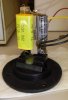
A70_New_Cap.jpg
 
Last edited:
Register to hide this ad
Pulled out my A70s to rotate into service for a bit and began mulling the technical aspects of these fine speakers. Not well versed in BA lore, I turned to the vast knowledge of the Web for enlightenment and am perplexed to discover no crossover schematic anywhere to be found. Seems odd for a very popular speaker enjoying ample buzz in the audio forums.

So it became a WTH moment, prompting me to pop one open and have a look. I have series I A70's, though with the Boston tweeter rather than earlier SEAS tweeter. The crossover in these is mounted on the terminal cup (unlike series II apparently). Mine look like this ...

View attachment 1749378

... with an air-core coil mounted on the reverse side:

View attachment 1749380

The coil is not labeled so I lifted some leads to measure it and the other components while already in there.
AND I traced out the schematic; to post here so I can find it next time I go looking.
View attachment 1751626

It's surprising to find this woofer runs free. Unexpected enough that I double checked. No mistake -- a red wire from the "+" terminal directly to the woofer "+", and a black wire likewise from the "-" terminal to the woofer "-." It is what it is, and seems to work well at that.

I Considered replacing those 37 year old caps but had no luck finding 6μF from the usual sources. Then I happened upon a couple from my parts bins. So I changed out the cap in the opened box. For now, its mate will retain the original cap for comparison. If it turns out the thing was better off before, I'll restore it as it was -- the original cap was left in place for that purpose.

View attachment 1749423
Your schematic just helped me out. I have this speaker. Since the woofer is driven "freely", I don't have to meticulously fuss over a replacement woofer impedance wise. Many speakers that I have seen have such an arrangement. I have no problem with that. Thanks for the schematic.
 
Thanks for the schematic.
Happy you found it useful.

Soon after my original post I discovered an unexpected woofer problem in the unopened A70. Very weak and distorted. Switched channels at the speakers' terminal connections and the problem didn't move. Not the amp or speaker wires -- problem's in the speaker.

While pondering replacement options I entertained non-stock woofer substitutions. Like yourself, I reasoned crossover issues would be minimal since they run free. But I never thoroughly explored specs for likely candidates, and have recently acquired a pair of stock woofers. Re-foaming them now. These bad boys will be singing shortly.
 
I have two pairs of BA 70 Series I with BA tweeters (both ~1983).

On average the resistance of the BA tweeters is 5.4 ohms
On average the inductors value seem to be 0,48 with some resistance 0.64 ohm.
I do not expect those values to be time sensitive a lot.

The original capacitor was 6.0uF.
I discovered that those original have an ESR at 1kHz of 1.1 ohm, I do not know if I should take this resistance in account.
Replacement capacitors seem to have less resistance which could change the sonic balance of the tweeter.

As stated in the specs by BA, the cross-over frequency is at 2000 Hz.

Now the tweeter is probably seen as a 6.4 ohms due to the 1 ohms resistance.

When using 2nd order butterworth formula, I end up with a capacitor value of 8.78uF and an inductor of 0,72.
Those values are quite different. How did BA arrived to those 6.0uF and 0,48 values ?

If I change the targetted cross-over frequency to 3000Hz, the values of the original parts make sense.

Are the specs wrong or am I missing something ?
 
I have two pairs of BA 70 Series I with BA tweeters (both ~1983).

On average the resistance of the BA tweeters is 5.4 ohms
On average the inductors value seem to be 0,48 with some resistance 0.64 ohm.
I do not expect those values to be time sensitive a lot.

The original capacitor was 6.0uF.
I discovered that those original have an ESR at 1kHz of 1.1 ohm, I do not know if I should take this resistance in account.
Replacement capacitors seem to have less resistance which could change the sonic balance of the tweeter.

As stated in the specs by BA, the cross-over frequency is at 2000 Hz.

Now the tweeter is probably seen as a 6.4 ohms due to the 1 ohms resistance.

When using 2nd order butterworth formula, I end up with a capacitor value of 8.78uF and an inductor of 0,72.
Those values are quite different. How did BA arrived to those 6.0uF and 0,48 values ?

If I change the targetted cross-over frequency to 3000Hz, the values of the original parts make sense.

Are the specs wrong or am I missing something ?

Online calculators are worthless unless you know the actual impedance at the desired crossover frequency. The 5.4 ohms you measured for the tweeter is the dc resistance, not the ac impedance, which varies with frequency.

As for the reduced ESR of film caps, many like to add a series resistor when recapping. Since you determined that the original cap's ESR was 1.1 ohms, you could add a 1 ohm resistor in series with the film cap. That will be close enough to give you equivalent attenuation as the original circuit.
 
Online calculators are worthless unless you know the actual impedance at the desired crossover frequency. The 5.4 ohms you measured for the tweeter is the dc resistance, not the ac impedance, which varies with frequency.

As for the reduced ESR of film caps, many like to add a series resistor when recapping. Since you determined that the original cap's ESR was 1.1 ohms, you could add a 1 ohm resistor in series with the film cap. That will be close enough to give you equivalent attenuation as the original circuit.

Thank you, a practical point of view is welcome.
I like my BAs so before changing anything, I want to learn more.
The last thing I want to do is give more work to the tweeters when introducing replacements parts.
I wished I could calculate the initial target of BA when they designed the 70.

I am not using online calculator, I am using the butterworth formula from a sound engineering book I bought long ago.
It clearly specifies RL is the "load DC resistance in ohms".
For sure, those are models, just a ball-park initial design.
There's always empirical adjustments when facing the final/production design.

The impedance of the tweeters at 2048hz is in average close to 8 ohms.
Adding the 1 ohm resistance to this justifies a capacitor value of 6.24uF (close enough)
but I end up with an inductor of 1.0 instead of 0.48.

I wish I could spy that cross-over in action! :-)
 
As an electrical engineer, I disagree with the info in your book regarding using dc resistance values for drivers. The variables for crossover equations are in complex form, that is, they are not simple dc variables, and that includes the driver impedance. For a second order filter, the values for capacitance and inductance vary depending upon the shape of the desired frequency response curve. The driver's voice coil impedance is based on the resistance and inductance of the coil, with the inductance contributing to the complex portion of the impedance value.

More than likely, the BA crossover was tested and tweaked to obtain the desired result. As you note, crossover formulas only take you so far. Testing, either by listening or using test equipment, is almost always required to dial in the crossover so it matches the drivers and the box.

If you really want to see the crossover in action, use software like REW to measure the real-world impact of various values.

Also, if you are not using exact values, it is instructive to model (calculate) the variance and then see how that variance translates to changes in the crossover frequency. For example, if one tweeter measures to have a 8.4 ohm impedance at 2 kHz and another tweeter has a 7.6 ohm impedance (a +/- 5% variation of the average 8 ohms), how does that affect the crossover frequency for identical crossover circuits? Then repeat the calculations using the tolerance for each of the components. It is possible to calculate the tolerance of the crossover frequency based on the tolerance of the components and devices in the circuit. I used to work as an instrumentation engineer and often had to calculate the overall tolerance for systems based on the tolerance of all the parts in the system.

I also point out that, for a second order filter, the location of the resistor affects the resulting frequency response of the circuit. The resistor (R2) in series with the driver voice coil has a significant impact on the crossover circuit, whereas the resistor (R1) in series with the crossover circuit (which includes the driver) affects the input impedance to the crossover with less impact on the frequency response other than attenuation. Additionally, the power dissipated through the resistors varies based on the location with the resistor in series with the crossover circuit dissipating more power because it is exposed to a greater frequency range signal from the amp.
 
All that above from RTally plus you may have to consider the acoustic response of the individual driver in the design. The tweeter is likely starting to roll up approaching the desired xover point (response increasing as the frequency tested increases). So the the xover components are selected in a way to blend the needed electrical roll up with the acoustic roll up that will sum to the desired slope.
 
All that above from RTally plus you may have to consider the acoustic response of the individual driver in the design. The tweeter is likely starting to roll up approaching the desired xover point (response increasing as the frequency tested increases). So the the xover components are selected in a way to blend the needed electrical roll up with the acoustic roll up that will sum to the desired slope.

Indeed, this could end up as a custom design exercise.
Knowing what you need is part of the game, the other part is to get it in matched pairs. We're running in stereo here. I suppose this explains why some loudspeakers are expansive, they had to build with matching pairs.

So far, I've discovered that the original 6.0 uF capacitors are still measuring at their nominal value + or - 5% which is pretty good.Does this means they meet their goal is something I'll try to verify soon.

"If it isn't broken, don't fixed it" applies in audio too.

So far, this exploration allowed me to discover that I have one suspicious tweeter (1 ohm less resistance & 50% less inductance).
My project may well end up to identify the best matching components/drivers to assemble the best pair of A70 I could with what I have.
Further down the track, I should be able to use the remaining cabinet within a more experimental "acoustic speaker" project.

Does the resistance & inductance of drivers fade over time ?
Measuring old drivers may lead to measurements significantly different than those of new units.
 
There are two parameters that will vary over time for electrolytic caps: capacitance value and equivalent series resistance (ESR). As electrolytic caps age, ESR increases, resulting in attenuation of the tweeter when used in a high pass filter. ESR varies with frequency, and test equipment that can measure ESR at audio frequencies is not common nor inexpensive. It is not uncommon for old electrolytic caps to measure within tolerance for capacitance value and way too high for ESR.

An RTA is a fine way to tell if the caps have degraded. The last way to determine if caps need to be replaced is a listening test. Sure, severely out of spec caps will result in a muffled sound. But caps that are out of spec, but not too bad, cannot always be heard. A case in point is a pair of KLH Model Fives that have not been recapped. The previous owner had them as his main speakers for several years and only replaced them 'cuz he bought some better, newer speakers. He thought they sounded fine. They do sound good, but I can tell that they need recapping, particularly when comparing them to my restored KLH Model Six, a speaker with the same tweeter.

Also, the voice coil in a driver is just a coil of wire. If the VC has not been damaged such that the windings are shorted, the resistance will not change over time. The only possible electrical degradation of a driver is loss of magnetism of the motor. Alnico magnets will lose their magnetic charge over time and if they are subjected to shock. Newer rare earth magnets, not so much.
 
There are two parameters that will vary over time for electrolytic caps...

Indeed, many sources agree with your point of view, the health of capacitors impacts the tonal balance of the whole loudspeaker.

The "weird" tweeter I found is alone in my "sample" of 4, so I presume the magnetism is not at fault. I think the coil of that tweeter isn't what it used to be. Sadly replacing this coil will be tougher than looking for substitutes tweeters.

I've been told that measuring the inductor is kind of useless in this design. First, nothing should be close to the field created by the inductor, so the resistors and the capacitor located under the inductor will impact the inductor. Second, passing a wire thru the center of an air-core inductor is non-sense or a very creative and unusual approach.

I think the BA accountant had more than just the final word on the design.
 
Finally my restoration project is moving after some surprises.
I wanted to have better terminals (spade,banana) to improve the signal received.
I removed the original cross-over from the original terminals, put in Solen 6.2 uF 250v caps.
During reinstall the new terminal-crossover structure was competing for space with the original woofer.
The space is really at premium in that cabinet, specially behind the woofer, where is also the terminal hole.

So I build a high-pass that fits behind the tweeter, the inductor is no more vertical to the speakers but it is a lot more away from the woofer.
The components are as the original design as much as modern components allowed, the layout is different.
One advantage of this is that both cross-over (in fact high-pass) are more identical than the originals.

Lucky I had two pairs, the most original pairs were not impacted by my experiments.

I bough a DATS to play with and learn more.

Here's the DATS summaries for:
- the original BA70 057144
- the original BA70 057144 components installed in another BA70 box 058170 that had more wool inside and a gasket for the woofer
- the original BA70 057144 components installed in cabinet 058170 with new crossover

So far, DATS suggests that the cabinet with more wool and a gasket for the woofer changes lightly the specs of the whole speaker.
f(s) lowers a little bit (0.5Hz) but the Q(ms) rises.
The new crossover seems to produce a slope of impedance very similar for the tweeter, the woofer slope is different.
The f(s) rise by 2 Hz and the Q(ms) drops significantly. My understanding is the "m" is related to the "mechanical" part of the Q.
I do not understand why that value would change that much, the cross-over is just a high-pass and the volume of the cabinet didn't change.

The listening session will come in a near future but first I wanted to know more knowledgeable people point of view.
Thank you.
 

Attachments

I realize this is an older thread, mucho gracias for the x-o diagram. Here are some random thoughts for anyone wrestling with a curbside find. Mine needed 11 ohms after replacing the caps and the more I listen, the woofer seems to roll off too high, and upon further thought even though the date on the woofers is right and square magnets ( nothing screams Boston or CTS like square magnets ) these weren't refoamed, they were reconed. Reconing is fine unless the woofers were really meant to have a certain sound. Or new cones are heavier = less output level. These sound nice, mids are clear, bass is deep and fairly articulate. From here trying random coils from basket case curb and thrift store finds. I have ears and spare time not any fancy testing stuff.
 
I picked up some empty A70 boxes and installed a tweeter and 2nd order x/o from a set of energy pro 2.1 speakers and paired them with a set of infinity woofers. I added 5 way terminals and stuffed the boxes a little more with some polyfill.

All contact surfaces sealed with silicon to make them air tight. I tested my home brew set vs. a series 1 set stock and my home brew set destroyed them in a side by side. They guy that bought them agreed and took away the home brew set.The bass was tighter and fuller.

I alway scoop the A70's with rotted foams for a song and enjoy them before relisting them. Sometimes the woofers are damaged due to running them without surrounds intact.


20260128_092128.jpg


At such a low price point and simple design to start they really do make ideal hobbyist speakers. Add some fill, remove some fill, play with different caps. run some sweeps, REW is good freeware online, and use your ears and compare.
 
Last edited:
Put some fresh surrounds on them and broke them in overnight. Threw a Nichicon muse series cap in place of the dying ones.
20260213_115653.jpg20260213_115739.jpg

The grills are in great shape. Another set saved from the junk heap.
 
Back
Top Bottom