

Hi,
I don't know if what I'm about to do will actually help AKers, PHONO preamp DIYers, and turntable NOOBs, but here it goes anyway.
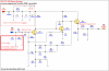
The Picture you see below is the schematic of a TCC TC-750 external phono preamp that someone created; you can view it online by doing a quick GOOGLE search. I own this preamp, and I'm using it in conjunction with a DIY linestage tube preamp I'm building.
This is an EXTERNAL phono preamp that uses an external 12volt wall-wart-style power supply.
The power from the wall wart power supply starts where it says 12vDC. There is a diode, then from there power goes to three caps (two of which are power supply filter caps and the third I think is a high frequency or RF filter cap) and one resistor. There is also a small circuit for the LED bulb; it tells you that the circuit is turned on and working. It consists of course of one LED and also one resistor.
OK, now take a look at the INPUT. What you are seeing is the LEFT INPUT. PHONO preamps have two channels - left and right. The power supply in this design powers both channels. So you have to imagine doubling everything outside of the 12vDC power supply circuit.
Right after the left INPUT is one cartridge loading loading capacitor and one cartridge loading resistor. These two components you can change to match the loading of your particular turntable cartridge. Notice how they are going straight to ground and ARE NOT is the signal path.
Now take a look at the first capacitor you see that IS in line with the INPUT signal. This is the INPUT capacitor. Many DIYers replace this with a fancy schmancy capacitor from WIMA or a NICHICON MUSE.
This PHONO preamp is an all 100% transistor based design There are three of them per channel. There's not one single OP-AMP present on the board. Many vintage receivers from the '70s used is type of a design. The next time you crack open your vintage receiver, check a look at the phono board - it should sport all transistors, and no OP-AMPs. I upgraded the transistors in my TCC TC-750 with lower noise transistors. I can't remember which ones I used now, it's been so long ago. LOL
Finally, look at the OUTPUT. The capacitor you see that is in line with the signal right at the end of the circuit is the OUTPUT capacitor. It too is a cap that many DIYers like to upgrade to a fancy schmancy capacitor.
So there you have it folks! 12volt wall wart power supply and accompanying filter caps and diode. The LED circuit. And finally the PHONO circuit itself that is an all 100% transistor based circuit design sporting cartridge loading and a few upgradeable input/output capacitors.
I hope this made things a little bit clearer! If I made any mistakes in my little rant here, please feel free to degrade me in the most passive-aggressive way possible.
I don't know if what I'm about to do will actually help AKers, PHONO preamp DIYers, and turntable NOOBs, but here it goes anyway.
The Picture you see below is the schematic of a TCC TC-750 external phono preamp that someone created; you can view it online by doing a quick GOOGLE search. I own this preamp, and I'm using it in conjunction with a DIY linestage tube preamp I'm building.
This is an EXTERNAL phono preamp that uses an external 12volt wall-wart-style power supply.
The power from the wall wart power supply starts where it says 12vDC. There is a diode, then from there power goes to three caps (two of which are power supply filter caps and the third I think is a high frequency or RF filter cap) and one resistor. There is also a small circuit for the LED bulb; it tells you that the circuit is turned on and working. It consists of course of one LED and also one resistor.
OK, now take a look at the INPUT. What you are seeing is the LEFT INPUT. PHONO preamps have two channels - left and right. The power supply in this design powers both channels. So you have to imagine doubling everything outside of the 12vDC power supply circuit.
Right after the left INPUT is one cartridge loading loading capacitor and one cartridge loading resistor. These two components you can change to match the loading of your particular turntable cartridge. Notice how they are going straight to ground and ARE NOT is the signal path.
Now take a look at the first capacitor you see that IS in line with the INPUT signal. This is the INPUT capacitor. Many DIYers replace this with a fancy schmancy capacitor from WIMA or a NICHICON MUSE.
This PHONO preamp is an all 100% transistor based design There are three of them per channel. There's not one single OP-AMP present on the board. Many vintage receivers from the '70s used is type of a design. The next time you crack open your vintage receiver, check a look at the phono board - it should sport all transistors, and no OP-AMPs. I upgraded the transistors in my TCC TC-750 with lower noise transistors. I can't remember which ones I used now, it's been so long ago. LOL
Finally, look at the OUTPUT. The capacitor you see that is in line with the signal right at the end of the circuit is the OUTPUT capacitor. It too is a cap that many DIYers like to upgrade to a fancy schmancy capacitor.
So there you have it folks! 12volt wall wart power supply and accompanying filter caps and diode. The LED circuit. And finally the PHONO circuit itself that is an all 100% transistor based circuit design sporting cartridge loading and a few upgradeable input/output capacitors.
I hope this made things a little bit clearer! If I made any mistakes in my little rant here, please feel free to degrade me in the most passive-aggressive way possible.
Last edited:

