


FireGuruMN
Active Member
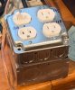
I have a variac on my bench and a bucking transformer also on my bench for when I am listening to a tube amplifier while restoring another project. I don't like to use the variac all the time because it buzzes and I use it too often on whatever I am restoring at the time. So I wanted to build another bucking transformer that I could put in my listening room for the really old tube equipment I use in there. Here is what I ended up with:
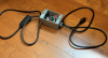
It's a heavy duty extension cord with a triple plug on one end (I have W5M mono amps so I need a few plugs) cut in half with the bucking transformer mounted in a weather proof electrical box. I chose the weatherproof box because a standard box has knockouts on it and those tend to get knocked in over time causing a safety issue. And the weatherproof box just looks neater. If I was really concerned about safety I would also add a fuse. If does look neat.
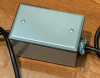
Back side with a couple of screws drilled to hold the transformer:
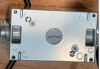
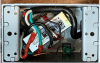
Here is the inside. Most people would use wire nuts but I'm more of a solder and heat shrink guy. I used crimp connectors to connect to the transformer. Solder would be better but when hooking up the transformer you never know which side of the output will give you a lower voltage and which will give you a higher voltage and slip on connectors make that change easier.
For those of you asking what the heck is a bucking transformer: It is usually a 12volt transformer wired back onto its self to lower the voltage on a the power source from the wall. Today most communities have 125vac coming out of the wall and back in the 50's and 60's it was only 110 or so. The bucking transformer will lower the voltage down to an acceptable without the need to have a huge transformer to handle the current.
Here is a picture from someone smarter and a better artist than me:
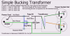
This diagram includes a fuse and light which are nice. It also allows for a couple different voltages on the output. I followed this diagram more so on my bench transformer but eliminated the options for the one pictured above. My bench one. It has a power switch, a straight 125v outlet, 117 and 110 outlets. Some amps are more sensitive than others. . .
And if they ever have a beauty contest for dim bulb testers I'm going to enter:
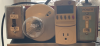
One thing I did WRONG, I wired my dim bulb tester before my variac. Then I would adjust the voltage on the variac high enough so I could bring my equipment I was testing on line. But the dim bulb tester was lowering the voltage and when I switch it to "full" the voltage would go back to normal 125vac and the variac might have been set to raise that even higher to 150vac. Very bad.
Always wire your dim bulb tester downstream of your variac.
The kill-a-watt is my way of checking current draw, voltage, wattage. It is plugged into a standard outlet. It's nice to have a continuous readout of voltage. And wattage can tell you if your equipment is drawing the current the specifications say it should. If it is drawings too much there is probably something wrong.
It's a heavy duty extension cord with a triple plug on one end (I have W5M mono amps so I need a few plugs) cut in half with the bucking transformer mounted in a weather proof electrical box. I chose the weatherproof box because a standard box has knockouts on it and those tend to get knocked in over time causing a safety issue. And the weatherproof box just looks neater. If I was really concerned about safety I would also add a fuse. If does look neat.
Back side with a couple of screws drilled to hold the transformer:
Here is the inside. Most people would use wire nuts but I'm more of a solder and heat shrink guy. I used crimp connectors to connect to the transformer. Solder would be better but when hooking up the transformer you never know which side of the output will give you a lower voltage and which will give you a higher voltage and slip on connectors make that change easier.
For those of you asking what the heck is a bucking transformer: It is usually a 12volt transformer wired back onto its self to lower the voltage on a the power source from the wall. Today most communities have 125vac coming out of the wall and back in the 50's and 60's it was only 110 or so. The bucking transformer will lower the voltage down to an acceptable without the need to have a huge transformer to handle the current.
Here is a picture from someone smarter and a better artist than me:
This diagram includes a fuse and light which are nice. It also allows for a couple different voltages on the output. I followed this diagram more so on my bench transformer but eliminated the options for the one pictured above. My bench one. It has a power switch, a straight 125v outlet, 117 and 110 outlets. Some amps are more sensitive than others. . .
And if they ever have a beauty contest for dim bulb testers I'm going to enter:
One thing I did WRONG, I wired my dim bulb tester before my variac. Then I would adjust the voltage on the variac high enough so I could bring my equipment I was testing on line. But the dim bulb tester was lowering the voltage and when I switch it to "full" the voltage would go back to normal 125vac and the variac might have been set to raise that even higher to 150vac. Very bad.
Always wire your dim bulb tester downstream of your variac.
The kill-a-watt is my way of checking current draw, voltage, wattage. It is plugged into a standard outlet. It's nice to have a continuous readout of voltage. And wattage can tell you if your equipment is drawing the current the specifications say it should. If it is drawings too much there is probably something wrong.


