• The move to the new server is done. There are some software and database maintenance updates in process. This has us passing the hat around to help out. We appreciate any donations. Seriously, even a dollar helps. The payment page may be found here - https://www.audiokarma.org/support.html

CA-F1 Preamp - Rough but Working

petesui

AK Subscriber
Subscriber
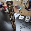
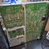
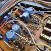
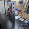
Delayed on the tarmac and scrolling in Denver last weekend, I had no choice but to make an offer on this beat up 120V CA-F1. My offer was accepted by the time I reached baggage claim. Unfortunately, our bags did not reach baggage claim. Anyway, delivery was quick from nearby Oregon. I struggle to imagine the rough life this unit has suffered. The covers are badly scarred with scratches, paint splatter, and dings. Missing screws, a little rust and oxidation in spots on the chassis. The rear panel is filthy and the inputs gunked with all 47 years worth of grime. The phono ground binding post was bent and loose having suffered some sort of blow. There's evidence of some history with the power cord given crimp marks on the cord and the chewed up strain relief. Somehow, the transformer even has scratches on it. The solder side of the boards are caked with old flux.

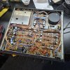
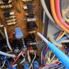
It appears completely original and, other than the power cord, I don't see any evidence of prior work or service. I've finally laid eyes on my first complement of the infamous black flag caps! I've yet to remove the phono stage cover. It passed the DBT fine and the DMM registered only a few mV of DC offset. I hooked it up to a thrifted Audio Source amp and the ugly Yammies, and it passes good clean sound through both channels on the tuner and aux inputs! There are, however, pretty consistent dropouts and relay clicking in and out as it continues to play. The controls are smooth and don't sound noisy although manipulating them does cause dropouts. Again though, the sound when present is generally clean and strong. Thus, I'll start with a thorough cleaning of the controls and scrubbing of the inputs - I suspect the contact here is very bad and the RCAs I was using were not a particularly snug fit. Assuming basic service restores consistent output, I'll move on (slowly) with further restoration from there. I've already flagged @Hyperion's CA-F1 thread which, as usual, is full of useful information and will lead me to other useful threads I'm sure. Now to find a service manual and schematic. Oh, and a BA-F1 of course!
Front.jpg
Dirty Rear Panel.jpg
Component Side.jpg
Black Flag.jpg
Solder Side.jpg
 
Register to hide this ad
I saw that one and almost bit, but condition is a main factor for me.

Hope you get it sorted out.

I’ll find one someday.

Rob
Thanks. Yeah, I think these are among the rarest of Sansui birds. They really don't seem to come up that much. I'm still early in my audio repair and restoration journey, barely out of my rookie year. Thus, I'm willing to take a flyer on something in rough condition for a low investment and more experience. Then I don't feel as uptight about it and can try to relax, but I get invested pretty quick once the covers come off! I'd been sitting in airports and on planes all day (and away from my Sansuis for more than a week!). Couldn't help myself.
 
Last edited:
You might find my restore thread useful. ;)
I just spent a fun couple of hours finding out why I couldn't zero the DC offset

but I was enjoying the chase, familiarising myself with the locations of components, and I was certain sure I wasn't going to be beaten.
A helpful perspective from your thread that I promise to work on adopting. I get so nervous and bound up in my shorts working on these things. It's supposed to be fun, right?! It's certainly a hard-won sense of accomplishment to figure it out and get something working right.
 
You've stumbled onto a true gem, notwithstanding any condition issues. A Ca-F1 has been in my primary system for a number of years following a comprehensive refurbishment, driving a BA-5000 as opposed to the matching BA-F1. The CA/BA combo is fantastic, and I ran that for a while, but the BA5K wins out for effortless power and the CA-F1 an extraordinary source for the older amp design, with a lush but detailed synergy. As you know, it is a very dense build, and will take some time to properly restore, but the effort is well worth it and it will undoubtably be a keeper once complete, whether the exterior cleans up well or not.
 
You've stumbled onto a true gem, notwithstanding any condition issues. A Ca-F1 has been in my primary system for a number of years following a comprehensive refurbishment, driving a BA-5000 as opposed to the matching BA-F1. The CA/BA combo is fantastic, and I ran that for a while, but the BA5K wins out for effortless power and the CA-F1 an extraordinary source for the older amp design, with a lush but detailed synergy. As you know, it is a very dense build, and will take some time to properly restore, but the effort is well worth it and it will undoubtably be a keeper once complete, whether the exterior cleans up well or not.
I've been thinking about how I'll use it. I do have a BA-2000 in one of my systems which I currently preamp with the AU-11000. Perhaps I'll run the CA-F1 into the BA-2000 for starters and return the 11000 to integrated status. I'm committed to taking my time with this CA-F1 restoration. There is no rush and I shall not create one! Despite its exterior condition, the internal electronic structure, boards, and traces appear to be in good sound shape. Other than glue, flux, and grime, I don't see any signs of previous trauma. It should clean up well inside. I'm also surprised by the very detailed silkscreen labeling on both sides of the boards. I certainly enjoy the cosmetically clean examples in my collection, but there's also an inherent cool factor to a rough hard-lived unit that still runs well as it should. Thanks, appreciate your motivating comment.
 
I wish you well in your restoration project. I have a CA-F1 in my Sansui collection of hi fi equipment. What I do is, utilize the very cool Sansui AX-7 which allows me to connect and switch three preamps to one main amp. Its easier to switch between preamps, unlike the main amp, they dont need to be wired to speakers, so everytime you select a different preamp, you dont have to then switch wires to another set of speakers, as you would when choosing different power amps.

I have a CA-F1, and also an AU-519 and AU-317 (both switched into preamp mode, from integrated), so I can choose either of them via the AX-7 to my BA-F1.

The F1 is a nice preamp, though the slim height means the knobs are small and there is no headphone capability for music listening. For me, I get a bit spoiled
by the deluxe size knobs as on my G-9000, AU-717, or the 519 and even the 317. The volume knob on the CA-F1 is the size of a tone knob on the 717. Not that its necessarily bad in an way, but a hefty volume control is preferable to me. One feature I would also prefer that the CA-F1 had- the ability to run the two pre outs the way it is on the CA-3000 or CA-2000, such as if one were to Bi-amp and wanted to have each pre out connect to its own amp so that one amp drives the woofers and the other the mid-highs. The F1 allows you to run A or B, but not together.

Ps- just make sure to remove/replace those 'black flag' caps. And you probably know, but just in case, the green power button does illuminate when turned on. It commonly goes out after time & age, so if you buy one from a seller, you might not know that it illuminates (as well on F1 power amp).
 
I wish you well in your restoration project. I have a CA-F1 in my Sansui collection of hi fi equipment. What I do is, utilize the very cool Sansui AX-7 which allows me to connect and switch three preamps to one main amp. Its easier to switch between preamps, unlike the main amp, they dont need to be wired to speakers, so everytime you select a different preamp, you dont have to then switch wires to another set of speakers, as you would when choosing different power amps.

I have a CA-F1, and also an AU-519 and AU-317 (both switched into preamp mode, from integrated), so I can choose either of them via the AX-7 to my BA-F1.

The F1 is a nice preamp, though the slim height means the knobs are small and there is no headphone capability for music listening. For me, I get a bit spoiled
by the deluxe size knobs as on my G-9000, AU-717, or the 519 and even the 317. The volume knob on the CA-F1 is the size of a tone knob on the 717. Not that its necessarily bad in an way, but a hefty volume control is preferable to me. One feature I would also prefer that the CA-F1 had- the ability to run the two pre outs the way it is on the CA-3000 or CA-2000, such as if one were to Bi-amp and wanted to have each pre out connect to its own amp so that one amp drives the woofers and the other the mid-highs. The F1 allows you to run A or B, but not together.

Ps- just make sure to remove/replace those 'black flag' caps. And you probably know, but just in case, the green power button does illuminate when turned on. It commonly goes out after time & age, so if you buy one from a seller, you might not know that it illuminates (as well on F1 power amp).
Thank you. I'm looking forward to it. I'll have to pick up an AX-7 next time I see one. I didn't realize it's usefulness in that regard. I understood it to be a mixing console for musicians. I use a couple of different black box amp and speaker switchers (like the Solupeak) to mix and match amps/receivers and speakers in my systems. I do have an MA-7 and the cue speakers, but it really only serves as glorified VU meters.

I had the same thought about the volume knob last night as I was reinstalling it. Even my humble AU-217 has a large knob that lends authority to the proceedings. My poor neglected AU-317 keeps getting displaced in the repair queue. First by the Eight, then the 551, and now the CA-F1.

I have the infamous black flags marked for sure. They are the first I've seen in any of my gear. I'm looking forward to finally replacing them after reading so much about them. I'm glad you mentioned the green power button. Is it the button itself that is the bulb and illuminates? Mine does not illuminate unfortunately. I pulled it off last night expecting to find a bulb underneath but there isn't one. There are two prongs behind the button. I was wondering if there is some kind of bulb that plugs into those prongs? Incidentally, the MA-7 has a red power button which I find odd for Sansui. It should be Sansui green.
 
Thank you. I'm looking forward to it. I'll have to pick up an AX-7 next time I see one. I didn't realize it's usefulness in that regard. I understood it to be a mixing console for musicians. I use a couple of different black box amp and speaker switchers (like the Solupeak) to mix and match amps/receivers and speakers in my systems. I do have an MA-7 and the cue speakers, but it really only serves as glorified VU meters.

I had the same thought about the volume knob last night as I was reinstalling it. Even my humble AU-217 has a large knob that lends authority to the proceedings. My poor neglected AU-317 keeps getting displaced in the repair queue. First by the Eight, then the 551, and now the CA-F1.

I have the infamous black flags marked for sure. They are the first I've seen in any of my gear. I'm looking forward to finally replacing them after reading so much about them. I'm glad you mentioned the green power button. Is it the button itself that is the bulb and illuminates? Mine does not illuminate unfortunately. I pulled it off last night expecting to find a bulb underneath but there isn't one. There are two prongs behind the button. I was wondering if there is some kind of bulb that plugs into those prongs? Incidentally, the MA-7 has a red power button which I find odd for Sansui. It should be Sansui green.
My tech friend worked on my BA & CA-F1 several years ago to replace the black flags and he also replaced the bulbs- I imagine there must be some kind of bulb within that illuminates when the power button is pressed on. The MA-7 is similar, just red instead of green.

The AX-7 is a useful device and matches well with the AU & TU amps made at the time within a GX-5 rack. You are correct that the AX-7 can be used by musicians to plug an electric guitar, keyboard or mics into, and it has reverb and so forth- but the AX-7 can do more when it comes to signal routing. If someone were to run out of inputs on their amp and needed extras to hook up multiple tape decks and whatnot, the AX-7 is quite beneficial to have.

The AX-7 can act passively as a switcher, meaning the power switch is not even needed to power it on. You can ignore the functions of doing home musician stuff with it, as it pertains to the controls on the right side of the unit and just switch between several hi fi components. The op manual does not even mention it, but as I said, you can connect three preamps to the tape rec/play jacks and alternate between them to one main amp.

There are also two Adaptor jacks, which I use to connect my MA-7 and SE-9 EQ to, for extra visual eye candy.
 
Good results from the control and input cleaning today. The CA-F1 is playing music from both channels cleanly without any dropouts or relay clicking in and out now. All controls working and noise free. Voltages on the power supply are -40.53/39.35V (+/-40V spec). Close enough for rock n roll. Now to check my stock and work on my Mouser order. Sound check linked here: Sansui CA-F1 Soundcheck
 
Last edited:
The two large black filter capacitors are now Nichicon KW's 3300µF, 63V (85°C) - Initially I was a bit concerned about using them as the PSU before restoration got VERY hot due to the heat from the series pass transistors. These transistors have now been replaced and I was pleased to note that the PSU now runs an order of magnitude cooler - hence the KW's were deemed suitable. I have left all the MOX resistors alone, they are all well within spec' and do their job well. Other items changed are seven electrolytic capacitors, one zener - replaced with a precision 2% type and, two trimmers. One of the trimmers was 680Ω (as marked) ! - I replaced this with a 500Ω without any issues. (the track resistance in use with the 680Ω trimmer was around 270Ω).

I note on the schematic for the main filter capacitors it says 'Note C601 & C602 = 1000µF, 63V, (Japan Model 2200µF, 63V)'. As you will note above they are now 3300µF, 63V as this is my rebuild spec' :king: other capacitors (with careful consideration) have received similar treatment, a restore methodology copied shamelessly from Ben, @Leestereo

I had already started doing this early on in my restorations, and like you I was unsure about how far I could go with value increases. Ben showed the way, and I subsequently used his excellent restoration technique, with a few tweaks of my own, to great effect.

@Hyperion I'm planning to follow your lead on C601/02 with my CA-F1. Having seen your references, as quoted above, to this methodology/philosophy a couple of times now, it occurs to me that I should understand the why, etc. Might you be able to direct me to a particular thread discussing this, or is it scattered throughout multiple threads? I'm not sure what to search for. Thanks.

I've ordered MJE15032/33 to replace TR603/04; UKW1J332 3300uF 63V for C601/02; 1N4735A for ZD601; and I've built several (for practice) new bridge rectifiers using UF4007 to replace D601. And trimmers, I have new trimmers. I'm never touching an original Sansui trimmer again. I've learned that lesson a few times already!
 
Might you be able to direct me to a particular thread discussing this, or is it scattered throughout multiple threads? I'm not sure what to search for. Thanks.
I don't think it is stated in full anywhere, but I'll give it a shot here.

The increasing of electrolytic values in some locations is something that you can do for the reduction of ripple voltages present on the various supply rails of an amplifier. For the main filter capacitors for example, there are several reasons why you might increase the value. Firstly to reduce the rectification ripple, and secondly to reduce the audio signal induced 'modulation' of the supply rails in time with loudness peaks of the music. Secondly, simply to fit the existing clamps, and the availability of values and voltages that we can purchase now. Additionally the 'look', a couple of tiny little replacement capacitors with lots of foam padding doesn't look great. Finally the values of some manufacturers capacitors tends to be at the bottom of the tolerance range, so you might buy a 12,000µF capacitor to replace say a 10,000µF original, only to find that its value is around 9,800µF - still inside its tolerance but actually lower in value than the one you are replacing! - so you start considering 15,000µF replacements instead. (then the question of 'inrush current' comes into play, that's a whole 'nuther subject!).

Often you will see the high current main rail supply fed to the power amplifier stage, and a resistor added in series with this supply, decoupled to ground with a capacitor of say 50 or 100µF and sometimes with the addition of a zener diode, to create a stable lower voltage supply for the differential input pair stage of the amplifier. If you look at this 'voltage reduced' rail with an oscilloscope while music is playing you can see the voltage going up and down, and being 'modulated' by the current draw of the output transistors - this is despite the resistor, decoupling capacitor and zener diode trying to hold the supply steady. Before the resistor you often have decoupling capacitors of maybe 470µF - one for the +ve rail and one for the -ve rail. Think how much more stable that differential stage supply could be (reduced distortion?) if those decoupling capacitors were increased to say 1,000µF. This is called 'Local Filtering' - you already have huge capacitors providing ripple reduction and smoothing, but the Local Filtering is just a little bit more, to make things even better. When the units were built they were built for a market niche, at war price-wise with the other major players, increased capacitor values would have cost money - so it wasn't done.

You can take this philosophy too far and in extreme cases destabilise the amplifier, or ruin the frequency response or 'voicing' of the output or other stages to which misguided attempts at this method have been applied. Generally, inter-stage coupling capacitors should be left alone. Other electrolytic capacitors have their values chosen more specifically for 'timing' purposes - like the capacitors used to delay speaker relay closing until output stage voltages have stabilised. Obviously you will gain nothing if you mess with this value, whenever there are 'R's and 'C's involved there are time constants to be aware of. There are others too, which are chosen with great care by the manufacturers and are 'off limits' for value increases - therefore you can really mess up an amplifier by using this philosophy with insufficient electronics knowledge.

A Warning...
The value changes suggested by Ben, (@Leestereo) in his restore threads can be followed, but not transferred to other models that he has not restored.

That's it in a nutshell, I hope this gives you the general idea behind these thoughtfully chosen value upgrades, and the complications that can arise if not done properly. ;)
 
Last edited:
A Warning...
The value changes suggested by Ben, (Leestereo) in his restore threads can be followed, but not transferred to other models that he has not restored.
Duly warned and absolutely understood.
That's it in a nutshell, I hope this gives you the general idea behind these thoughtfully chosen value upgrades, and the complications that can arise if not done properly.
Well done and thank you so much. Exactly what I was looking for, and it's something I'll read several times to unpack and digest. I'm no where near experienced or knowledgeable enough in electronic circuitry to be formulating and making these decisions on my own. I'm little more than a reasonably handy apprentice audio mechanic at this point. I have a long long way to go in understanding the engineering part. Realizing that I was planning to triple the capacitance value of the main filter caps, I didn't want to follow along blindly (AI has already taught me some harsh lessons in that regard!) just because I saw it in your thread. Thus, I thought I should try to understand why. Many thanks for your time and thoughtful explanation. Parts are due today! Off we go.
 
Last edited:
I am just a mere mortal here among the technical giants like @Hyperion and @Leestereo and the other more accomplished technician builders, but I do have two cents to add. Having worked through quite a few restorations with Ben's guidance one other thing to keep an eye on when increasing capacitance of the mains is the current rating of the power switch - those bigger caps vacuum up a lot more juice when they first power up and that can overwhelm the power switch contacts. In my cases I was able to divide the load by running power in parallel from one to the two sets switch contacts (if available).
 
Last edited:
Satisfying progress today. Rebuilt F-2994 power supply. Started with installing new preset trimmers and dialing in rail voltage. Then cleaned a little glue under the small electrolytics and installed the new caps. All original caps were solidly within spec, although gluey. Moved on to the ZD and my UF4007 rectifier. Finally, the series pass transistors, followed by the new 3300uF main filter caps. Powered on the DBT after every group and all was good. The bulb charged slowly on the original 1000uF caps, but it sure snapped to with the new 3300uF caps. Rail voltage set to +/-40V spec, rock steady. Oh, and I replaced the dozen black flags last night just so they're out of the way off the bat.

I must say, this unit is a pleasure to work on compared to some of the earlier gear I've worked on so far (I'm looking at you my precious little Eight). The boards are spacious, clearly labeled on each side making solder joints easy to identify, and the pads and traces are very robust with plenty of room to flow (I still see you, Eight). Moving on to F-2993 tone and flat amp tomorrow. The site's not letting me upload progress pics at the moment, but they're nothing you haven't seen many times before. To be continued . . .
 
Back
Top Bottom