• The move to the new server is done. There are some software and database maintenance updates in process. This has us passing the hat around to help out. We appreciate any donations. Seriously, even a dollar helps. The payment page may be found here - https://www.audiokarma.org/support.html

Cad new Yamaha CR-2020 capacitor board

niclasf

New Member
Hi,

My first post here.

I have bought a vintage amp (cr-2020) at an auction.
I am familiar with electronics but mostly digital electronics. But I have also made five or so recappings of other vintage amps so I do have experience.

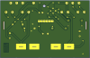
In the Yamaha it turns out that the e-cap pcb is in very bad shape, so I started to cad a new board in KiCad. Then it hit me that someone might have done this before.

Do anyone of you know if it has been done already the e-cap pcb for the cr-2020 and if there is one for sale?
 
Register to hide this ad
NICE! I remember seeing somewhere that Merrylander made his own PCB and there was a primitive picture of his PCB.

Do you have any clue how much this would cost?
 
I ordered 10 small pcb's from a place called pcbway.com and it was only about $15 total including s&h. I'm not sure how big this board is. Mine was only about 2 x 3 inches.
 
I am ordering from JLCPCB and the cost for 5 pcs is 25euro including shipping to Sweden.
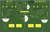
The bord is close to a copy of the original when it comes to placement of the components.
I have done a few changes.

1. sprinkled vias around through holes were hot components will be mounted.
2. terminals are screw terminals instead of solder lugs.
3. added a ground plane
4. 2-layers used to get rid of jumpers.
 
Last edited:
I will have the boards in 8 days.
Cost will be €5 +shipping

I ordered 5. There are 3 left.

note however that I do not know yet if they are working.
 
If you are selling your extra's i would be in for a set. I started a rebuild and my power supply boards look like they've been burned to a crisp. Someone also preformed a hack job trying to restore before i got my hands on it.
 
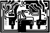
If a small modification is made to the mounts for those big filter caps, it's possible to use 5-lug snap-in replacements (e.g. https://www.mouser.com/ProductDetai...82LX183M100B082VS?qs=fupM46RXT604Tu029Z7KpQ==) that are really easy to mount and solder. An AK user posted this kind of design for a custom board years ago (https://audiokarma.org/forums/index.php?threads/yamaha-cr-2020-main-filter-cap-replacements.414955/) which I used recently to etch a new board. It worked great after vectorizing the mask image.

It won't let me upload the vector file but the attached pic is the basic idea. The un-connected circular pad between the + and - legs is for the middle lug.

Etching a new board was a massive pain the in the butt, won't make that mistake again even if it means learning kicad. Having one manufactured is cheaper and better.
 

Attachments

  • Yamaha CR2020A3_single_realsize.png
    Yamaha CR2020A3_single_realsize.png
    72.9 KB · Views: 128
Hint: AK has a limited amount of file type options for uploading but a zip-file always works. :)

Cheers,
James
 
So it does! Here's the svg. The perfectly smooth edges make for a good mask.

If it's printed at 136mm x 90mm, the outside edges of the side traces will match up exactly with the original board, although it ended up being stretched by a few mm top to bottom. It's the horizontal size that matters most so I just left it tall.
 

Attachments

Good suggestion regarding 5-pin snap-in capacitors. I have done the modification to the PCB so that it will fit.

However, when I did the modification I noticed that something was wrong with the PCB i ordered v1.1. I assumed that the pins where centered symmetric around the center of the capacitor circumference. It seem like it is not. the solder lugs are offset by 5.2mm and thus the original capacitors will make the PCB being 5.2mm too high up. This might work, but it might as well not work :/

I will look over my PCB v1.2 with snap-in mounts and order a new batch when I feel certain that it is correct this time :)
 
However, when I did the modification I noticed that something was wrong with the PCB i ordered v1.1. I assumed that the pins where centered symmetric around the center of the capacitor circumference. It seem like it is not. the solder lugs are offset by 5.2mm and thus the original capacitors will make the PCB being 5.2mm too high up.

I was wrong. Now with the PCB at hand it fits perfectly. The only thing that was affected was the silkscreen print on the PCB.

I did a quick test and soldered the big capacitors, the 6-pin header. I also just placed the ss-7, ss7r, bridge and screw terminals. Gravity pulls the terminals so that they point down, but that will not happen when they are soldered.

IMG_1463.jpg IMG_1464.jpg

Send me PM for more information.
 
It's perfect, well done!

Maybe you already have this, but here's the BOM from building my homemade board. The only parts I ended up reusing from the original board were the SS-7/SS-7R dual rectifiers, the 6-pin header, and the white insulation sleeve around one of the 4.7k resistors (although I did find a replacement for the 6-pin header later on).
Ended up using some turrets to replace the wire eyelets at the top of the board, it works fine as long as they don't get too hot. Using terminal blocks is an interesting idea though, that'd make it a lot easier to disconnect and reconnect the board for troubleshooting. Maybe put some loctite on the terminal screws if the wires are gonna be fixed that way long term.

If the SS-7s get damaged somehow or aren't working it turns out you can actually use FREDs to replace them, but it's kinda janky. If the original parts are working fine there's no reason to do this (https://www.audiokarma.org/forums/i...-120hz-hum-in-a-cr-2020.913429/#post-13783207).

I ended up mounting my 33/22ohm resistors on the wrong side of the board (facing the transfomer) similar to how oilmaster did it here: https://audiokarma.org/forums/index...-41vdc-on-outputs.787761/page-3#post-10992603. The 3-1/4W resistors are too big to fit in the space between the horizontal and vertical boards, and they cook the relay board in that location anyway. I'll put some reflective tape on the transformer, hopefully that will help keep it from absorbing too much of the heat.
 
Back
Top Bottom