EmuMannen
Member
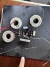
I got a pair of BIC SoundSpan TPR-600 that I got from a friend (who bought them new in the 70s). I was considering an XO upgrade or to go active, so I took a look at the original XO. But I can't wrap my head around it! Please take a look at the attached image. Red wire to woofer, green to mid and white to tweeter. They all share the black as the negative pole.
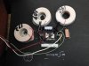
First of all, the markings on the coils; 109, 142 and 172? 109 can't be 10x10^9 so I'm a bit baffled. But what I find really puzzling is the fact that this 3-way XO only got one capacitor! The total amount of components and their values are; 1 capacitor 10uF, two resistors 2 and 4.7 Ohms, three coils marked 109, 142 and 172. I don't get it...
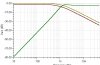
So I stuck the circuit with my assumptions into TINA-TI and ran a simulation. The circuit and the resulting graph are also attached. It sure didn't make me any wiser because it looks like the tweeter got a low-pass filter. What am I missing here? Has anyone ever seen a 3-way XO with only one cap? Or with a cap, two resistors and three coils in total?


Thanks in advance for any help.
First of all, the markings on the coils; 109, 142 and 172? 109 can't be 10x10^9 so I'm a bit baffled. But what I find really puzzling is the fact that this 3-way XO only got one capacitor! The total amount of components and their values are; 1 capacitor 10uF, two resistors 2 and 4.7 Ohms, three coils marked 109, 142 and 172. I don't get it...
So I stuck the circuit with my assumptions into TINA-TI and ran a simulation. The circuit and the resulting graph are also attached. It sure didn't make me any wiser because it looks like the tweeter got a low-pass filter. What am I missing here? Has anyone ever seen a 3-way XO with only one cap? Or with a cap, two resistors and three coils in total?
Thanks in advance for any help.