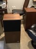
Hello, I’m new here and I hope I’m not in the wrong forum....lol. Can anyone direct me to finding a replacement rear speaker clip/clamp for a Pioneer CS-R700. Just picked them up today, they sound amazing !! Thank you !


You are using an out of date browser. It may not display this or other websites correctly.
You should upgrade or use an alternative browser.
You should upgrade or use an alternative browser.

Register to hide this ad


century tek
Addicted Member
You wouldn't have to open up the back of the speaker per say, but just take the screws out of the controls and connections plate. It should expose everything right there for you.


gdmoore28
Super Member
As others have pointed out, depending on what those input plates look like on the inside (post a pic), binding posts would be the way to go. If those current spring-posts aren't incorporated into a circuit board, it'd be an easy deal to drill the holes out to accept the posts. If the current posts are part of a circuit board, you could simply install them somewhere else on the input plate, or the speaker back panel itself.
And, welcome to AK!
GeeDeeEmm

And, welcome to AK!
GeeDeeEmm


 Are you a novice?
DaveVoorhis
Addicted Member
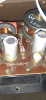
It's not clear in the picture -- how are the existing clips attached to the circuit board?I am....any tips? I guess I would like to convert them over to banana clips?
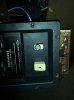
Looks like they're attached with Philips screws -- one labelled (+) and the other (-) -- but I'd like to make sure before making suggestions.
DaveVoorhis
Addicted Member
It doesn't answer my question, but assuming the Philips screws labelled (+) and (-) screw into the existing binding clips, unscrew them. The binding clips should come out. Then obtain binding posts like those shown in post #6, above. Unscrew the smaller nut at the end, pass the threaded end of the binding post through the screw hole in the circuit board -- which you may have to enlarge with a drill -- and fasten with the nut. If drilling out the screw holes has removed the conductors on the circuit board, you may have to get clever with washers or soldered leads to restore connectivity.How is this?
If this all sounds easy, excellent. Go to it!
If it sounds difficult, it's probably best to get someone to help you.
DaveVoorhis
Addicted Member
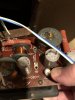
Yes, that confirms my assumption in post #14, which should provide the information you need.It appears the zoomed in picture, where it says input + & - is the backside of where the clips are connected. Does that help? Thank you

likebike23
Addicted Member
I would remove the knobs for the mid and low controls. There will be a nut under the knob, remove that. You can then remove the screws holding the board to the plate. Take a picture of the side if the board that was obscured by the black plate and post it.
Once everyone can see exactly what's going on they can give recommendations on what might be the best way to proceed.
Once everyone can see exactly what's going on they can give recommendations on what might be the best way to proceed.
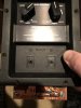
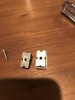
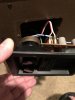
Removing the clips/connectors by the screw on the backside of the board allowed the clips to fall right off. It would take 8 more screws (covered in a brown glue) to allow the board to come free of the back panel. I’m not sure what route to go or which connectors to buy at this point. Thanks
Attachments
DaveVoorhis
Addicted Member
Get these: https://www.amazon.co.uk/KEESIN-Binding-Connector-Speaker-Amplifierr-Type-C/dp/B078C7H7Q5Removing the clips/connectors by the screw on the backside of the board allowed the clips to fall right off. It would take 8 more screws (covered in a brown glue) to allow the board to come free of the back panel. I’m not sure what route to go or which connectors to buy at this point. Thanks
See my instructions in post #14.
You may need to cut/drill some plastic, or you may not.