• The move to the new server is done. There are some software and database maintenance updates in process. This has us passing the hat around to help out. We appreciate any donations. Seriously, even a dollar helps. The payment page may be found here - https://www.audiokarma.org/support.html

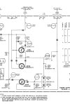
Can someone explain this voltage regulator circuit? Fisher 301 receiver

Carbsandcaps

Super Member
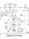
This is on a fisher 301 receiver. I was working fine until I decided to recap it and I accidentally hooked up the 14v tuner circuit (DD on the diagram) to, well, something else. It went poof now I only have about 6 volts out of that circuit. I’ve replaced the 15v zener diodes and tested the 3 transistors in the circuit. So far so good. At R960 I have 60 volts on one side and 6 on the other which is where the problem starts. I’m trying to figure out how this circuit works, obviously it uses the zener diodes for voltage regulation but for the life of me I can’t ignite out how.
 

Attachments

  • IMG_9743.jpeg
    IMG_9743.jpeg
    87 KB · Views: 62
Register to hide this ad
What voltage are you seeing at BB and CC?
It's pointing towards Q951 not conducting collector to emitter.
Unfortunately I don’t have the receiver with me now I’ll have to check tomorrow. I just did a quick check with a multimeter with the transistors still in the circuit. I’m just confused as to how that circuit drops 60v down to 14
 
The 35V at the top of the 2 zeners comes from the output of Q951 (- drops through the resistors). The 2 zeners act as a constant voltage divider between the 35v point (R963, R961, C956) and ground. 35v - 20 = 15, but it cannot raise it's cathode above 15volts because the lower 15v zener locks the divider centre point at a maximum of 15volts above ground potential. If the voltage applied at the top of the zener chain is lower than 35 volts, the divider centre point will be low as the 2 zeners cannot reach their avalanche point. If the voltage applied is above 35volts the centre point voltage will still be 15 volts.
 
Q951 is a current source for the two Zener diodes connected in series. The 15V Zener provides the reference voltage at the base of Q953 for the +14V output, and the 20V Zener, in series with the 15V Zener, provides the +36V reference voltage at the base of Q952, for the +35V output. R961 and R963 provide an additionnal 1V to the +35V Zeners and thermal compensation for the Zener diodes.

If you have only +6V at the collector of Q951, it means that Q951 is bad (you tested it good) or R958 is probably open.
 
So am I correct in assuming that q951 and q952 are there to make sure the voltage stays constant no matter the load?
 
Note that one zener is 20V and the other is 15V, you imply that your replaced both with 15V zeners. Did you get the polarity right on the zeners? Are you sure they're not shorted?
 
Note that one zener is 20V and the other is 15V, you imply that your replaced both with 15V zeners. Did you get the polarity right on the zeners? Are you sure they're not shorted?
Yes I just noticed I replaced both with a 15v polarity is correct I’m changing them out now
 
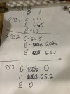
So I’m batting 1000 here. I had the wrong schematic. The 301 and 401 are the same receiver with the 401 having the auto tune preset fisher thing. Both are lumped together in the same manual with a small number at the bottom. I posted the 401 schematic instead of the 301 which uses the same circuit but different values I’m assuming because they don’t need to power the auto tuner.
 

Attachments

  • IMG_9752.jpeg
    IMG_9752.jpeg
    79.3 KB · Views: 8
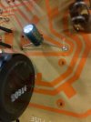
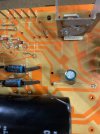
GOT IT! Capacitor c956 was labeled backwards on the board and since it connects directly to the zeners it was dragging the voltage down. I used a 100v cap in that place because that’s all I had so it wouldn’t have blown up but it was enough to drag the voltage down. Once noticed it on the diagram I swapped it around and my voltages are back! Thanks so much guys! I learned a lot from you! IMG_9755.jpegIMG_9756.jpeg
 
Back
Top Bottom