• The move to the new server is done. There are some software and database maintenance updates in process. This has us passing the hat around to help out. We appreciate any donations. Seriously, even a dollar helps. The payment page may be found here - https://www.audiokarma.org/support.html

Can someone help me with choosing a resistor value?

MOEB74

Active Member
I have my SE-A70 recapped and had them install some LED kit from ebay. Good feedback etc from the seller, but I feel they're too bright and appear to be giving off more heat than I would think for LEDs. With that being said, can someone help me figure out what resistor I would need?

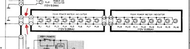
There is also two jumper wires in the middle of the two lamp circuit boards ( connecting the two boards ), Cant I put the resistor there, between the two boards? Or does it have to go on the positive or negative leads at the "start", coming off of the board?
 
Register to hide this ad
Lot of lamps in there.

se70lamp.jpg


Since the power for these is AC the LED's would have a diode and a dropping resistor of x value. x is what we don't know.
Any idea what they used to replace the old bulbs with?

I am going to take a guess so it won't be 100% accurate. I am assuming they replaced the lamps 1 for 1 so 16 LED's in parallel drawing (here is the guess) 10ma each would be 160ma total draw. That comes to what would be equivalent to a 75 ohm resistor. FYI 160ma at 12 volts is 1.2 watts so a bit of heat.

We are dealing with some form of at the very least half wave rectified (in the LED) pulsing/unfiltered AC so the values are not exact.

To drop the current flow in half we would need another 75 ohm resistor of at least 1 watts value. It should be dissipating close to 1/2 watt.

I would try a 100 ohm at one watts and see where that lands you. It has to be installed in one of the main leads not the jumper.

There are other variables at play here that would effect the numbers but I think this should be close if they used 16 LED's, if it is less the calculations will change.

Too bad it is AC. you could get a small 12 volt PWM dimmer and have them adjustable from off to 100%

I think this is close, If I am off somewhere I'm sure somebody will correct me :D
 
I'd err on the side of caution, go with 20mA/LED draw say 300mA. Certainly part number or datasheet of the replacement would help. Maybe drop 1-2V say 6.8ohms? 1-2W rating?
 
Lot of lamps in there.

View attachment 3825183


Since the power for these is AC the LED's would have a diode and a dropping resistor of x value. x is what we don't know.
Any idea what they used to replace the old bulbs with?

I am going to take a guess so it won't be 100% accurate. I am assuming they replaced the lamps 1 for 1 so 16 LED's in parallel drawing (here is the guess) 10ma each would be 160ma total draw. That comes to what would be equivalent to a 75 ohm resistor. FYI 160ma at 12 volts is 1.2 watts so a bit of heat.

We are dealing with some form of at the very least half wave rectified (in the LED) pulsing/unfiltered AC so the values are not exact.

To drop the current flow in half we would need another 75 ohm resistor of at least 1 watts value. It should be dissipating close to 1/2 watt.

I would try a 100 ohm at one watts and see where that lands you. It has to be installed in one of the main leads not the jumper.

There are other variables at play here that would effect the numbers but I think this should be close if they used 16 LED's, if it is less the calculations will change.

Too bad it is AC. you could get a small 12 volt PWM dimmer and have them adjustable from off to 100%

I think this is close, If I am off somewhere I'm sure somebody will correct me :D
I'd err on the side of caution, go with 20mA/LED draw say 300mA. Certainly part number or datasheet of the replacement would help. Maybe drop 1-2V say 6.8ohms? 1-2W rating?

Thanks guys, maybe if its too much heat coming from the resistor, Id rather just leave it as is then. Would the axial bulbs run hotter? Im guessing so since they're 55ma per and, like you guys stated, there is 16 total.
 
Thanks guys, maybe if its too much heat coming from the resistor, Id rather just leave it as is then. Would the axial bulbs run hotter? Im guessing so since they're 55ma per and, like you guys stated, there is 16 total.
I can pretty much guarantee the incandescents ran hotter than the LEDs' and a dropping resistor will.
 
If the heat from a single resistor is too much, you can spread it across two. Instead of a single 6.8 ohm replacing one jumper, two 3.3 ohms, replacing each jumper would be near enough to the same.

Same total heat dissipation, just spread out more.
 
If the heat from a single resistor is too much, you can spread it across two. Instead of a single 6.8 ohm replacing one jumper, two 3.3 ohms, replacing each jumper would be near enough to the same.

Same total heat dissipation, just spread out more.
Thanks! Can I use a variable resistor?
 
Lot of lamps in there.

View attachment 3825183


Since the power for these is AC the LED's would have a diode and a dropping resistor of x value. x is what we don't know.
Any idea what they used to replace the old bulbs with?

I am going to take a guess so it won't be 100% accurate. I am assuming they replaced the lamps 1 for 1 so 16 LED's in parallel drawing (here is the guess) 10ma each would be 160ma total draw. That comes to what would be equivalent to a 75 ohm resistor. FYI 160ma at 12 volts is 1.2 watts so a bit of heat.

We are dealing with some form of at the very least half wave rectified (in the LED) pulsing/unfiltered AC so the values are not exact.

To drop the current flow in half we would need another 75 ohm resistor of at least 1 watts value. It should be dissipating close to 1/2 watt.

I would try a 100 ohm at one watts and see where that lands you. It has to be installed in one of the main leads not the jumper.

There are other variables at play here that would effect the numbers but I think this should be close if they used 16 LED's, if it is less the calculations will change.

Too bad it is AC. you could get a small 12 volt PWM dimmer and have them adjustable from off to 100%

I think this is close, If I am off somewhere I'm sure somebody will correct me :D
A pwm dimmer would me much preferable instead of cooking of a bunch of energy as heat.
I assume the AC is half or full wave rectified before reaching the LEDs. -They shouldn't be exposed to inverse voltages in any case.
Example: Robot or human?
 
A pwm dimmer would me much preferable instead of cooking of a bunch of energy as heat.
I assume the AC is half or full wave rectified before reaching the LEDs. -They shouldn't be exposed to inverse voltages in any case.
Example: Robot or human?
According to the schematic the original lamps are AC powered. We don't know if the tech who upgraded them used AC powered LEDs, or added a common rectifier.

It would be fairly simple to add a rectifier and small PWM module to the system but I don't know if @MOEB74 wants to or is able to go down that path.
 
According to the schematic the original lamps are AC powered. We don't know if the tech who upgraded them used AC powered LEDs, or added a common rectifier.

It would be fairly simple to add a rectifier and small PWM module to the system but I don't know if @MOEB74 wants to or is able to go down that path.
Looks like they were internally commutated and controlled.
 
They were these from eBay. So plug and play essentially

OK that helps a bit. With three LED chips per lamp I can see where they are probably brighter.

Since they are 8 to 24 V, how well will a resistor work?
The ebay ad states 8-14 volts not 8-24 (typo?) It simply means that they will work in that range of voltages. Typically the higher the voltage the brighter they will be.

And yes a simple resistor should work fine. If you are considering adding one you can simply test a couple of values and see what works best.
 
OK that helps a bit. With three LED chips per lamp I can see where they are probably brighter.


The ebay ad states 8-14 volts not 8-24 (typo?) It simply means that they will work in that range of voltages. Typically the higher the voltage the brighter they will be.

And yes a simple resistor should work fine. If you are considering adding one you can simply test a couple of values and see what works best.
Thtas what I was thinking but dont know where to start... They should be 2w or 1w? How do we, I, determine what value wattage to use?
 
Without knowing what current values we are working with I can't be exact. 1 Watt should be plenty safe for experimenting.
Once you find the value that works for you then measure the voltage drop across the resistor and use ohms law to calculate the power dissipation and see if you are in the safe zone.

Safe zone rule of thumb for me is a rating of around twice the actual dissipation. So a safe dissipation for a 1 watt resistor would be in the neighborhood of 1/2 watt.
 
Without knowing what current values we are working with I can't be exact. 1 Watt should be plenty safe for experimenting.
Once you find the value that works for you then measure the voltage drop across the resistor and use ohms law to calculate the power dissipation and see if you are in the safe zone.

Safe zone rule of thumb for me is a rating of around twice the actual dissipation. So a safe dissipation for a 1 watt resistor would be in the neighborhood of 1/2 watt.
Understood. Im an "overhead" guy, if its worth building its worth overbuilding. In this case, Id rather get a more stout resistor for more safety/overhead.
 
you can buy a box of assorted resistors in 1 or 2 watts. if you keep the leads long while experimenting on the value, you can reuse the resistors that you don't install.
 
you can buy a box of assorted resistors in 1 or 2 watts. if you keep the leads long while experimenting on the value, you can reuse the resistors that you don't install.
I have a bunch here already. So that’s not an issue. I’m just hoping I have some decent sizes
 
Thanks! Can I use a variable resistor?
so long as its high enough wattage, yes. I've used variables to set things where I want them, measured the value, and installed a fixed resistor.

can also just pull the jumper and use a couple of clip leads to bring out the connection to try some fixed resistors and go with whatever value looks right.
 
Back
Top Bottom