• The move to the new server is done. There are some software and database maintenance updates in process. This has us passing the hat around to help out. We appreciate any donations. Seriously, even a dollar helps. The payment page may be found here - https://www.audiokarma.org/support.html

Can someone please help. Jvc vr-5505

Old thread, but I thought I'd add a few comments for others who are working on one of these. I just finished cleaning up a VR-5505 and found a few things:

- There are 4 - 2SC458 transistors on the phono preamp. I changed them out for KSC1845s which eliminated noise issues.
- I also replaced the 2 - 2SC458s on the tone board since the ones on the phono board were noisy.
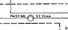
- All 8 of the small indicator lamps for speaker/source were out - they are supposed to be 6V 35mA but I substituted 12V 70mA which are readily available (cheap) and worked well. Bright enough and they draw about 40mA at 6.9VAC which is what I measured for actual voltage.
- Dial lamps were also out. The schematic shows 8V 150mA which are not very common so I used 6.3V 150mA (#40) lamps. I know they won't last as long with the measured 6.9VAC supply, but they are easy to change and readily available.
- The stereo lamp was not working - I replace it with the proper 6V 35mA lamp since that circuit can be a bit sensitive. I also replaced the 4 - 2SC711 transistors in that section of the tuner. One read really low hfe so they all went. I used 2SC945s (KSC945). Worked perfectly.
- Grounding: The grounding in this receiver had me scratching my head for a while. The speaker outputs, the tuner and all of the lamps are shown with chassis grounding points, but the rest of the circuits including amp and power supply don't connect to chassis ground at all according to the schematic. Some resistance measurements seemed to confirm that everything was, in fact, grounded through the chassis, so I added ground straps to various places to ensure good grounding. Not surprisingly, voltage reading that were somewhat erratic when I started working on it all became very stable. The tuner in particular was working intermittently with B+ voltages all over the place - that was resolved with improved grounding.

I suspect the OPs issues with fading output may have been related to the grounding issues I found . . . Maybe not, but something to consider if you work on one of these.

Rich
 

Attachments

Old thread, but I thought I'd add a few comments for others who are working on one of these. I just finished cleaning up a VR-5505 and found a few things:

- There are 4 - 2SC458 transistors on the phono preamp. I changed them out for KSC1845s which eliminated noise issues.
- I also replaced the 2 - 2SC458s on the tone board since the ones on the phono board were noisy.
- All 8 of the small indicator lamps for speaker/source were out - they are supposed to be 6V 35mA but I substituted 12V 70mA which are readily available (cheap) and worked well. Bright enough and they draw about 40mA at 6.9VAC which is what I measured for actual voltage.
- Dial lamps were also out. The schematic shows 8V 150mA which are not very common so I used 6.3V 150mA (#40) lamps. I know they won't last as long with the measured 6.9VAC supply, but they are easy to change and readily available.
- The stereo lamp was not working - I replace it with the proper 6V 35mA lamp since that circuit can be a bit sensitive. I also replaced the 4 - 2SC711 transistors in that section of the tuner. One read really low hfe so they all went. I used 2SC945s (KSC945). Worked perfectly.
- Grounding: The grounding in this receiver had me scratching my head for a while. The speaker outputs, the tuner and all of the lamps are shown with chassis grounding points, but the rest of the circuits including amp and power supply don't connect to chassis ground at all according to the schematic. Some resistance measurements seemed to confirm that everything was, in fact, grounded through the chassis, so I added ground straps to various places to ensure good grounding. Not surprisingly, voltage reading that were somewhat erratic when I started working on it all became very stable. The tuner in particular was working intermittently with B+ voltages all over the place - that was resolved with improved grounding.

I suspect the OPs issues with fading output may have been related to the grounding issues I found . . . Maybe not, but something to consider if you work on one of these.

Rich
Hi. I just picked one of these up today. Only one of those 8 source/speaker bulbs works and a couple fell off. Where/what bulbs did you get? Do you unsolder the old ones and the new ones you could solder back on?

I also am getting dc offsets in the 250mV. Should I be concerned? Anything specifically I should check to fix it? Thanks
 
Do a search on ebay or amazon for '12v grain of wheat bulb'. Unsolder what's left of the old bulbs, clean off the glue and solder in the new ones. I used a little hot glue to strengthen them after i soldered them.

DC offset of 250 mV is pretty high, but i don't believe it's adjustable on this model. Smarter folks than me can help with that, but start with verifying the + and - power rails are correct. (~ +18.5V/-18.5V). Maybe the driver transistors have drifted apart over time . . . . start here: https://www.audiokarma.org/forums/index.php?threads/amplifier-distortion-dc-offset-and-you.5634/
 
Do a search on ebay or amazon for '12v grain of wheat bulb'. Unsolder what's left of the old bulbs, clean off the glue and solder in the new ones. I used a little hot glue to strengthen them after i soldered them.

DC offset of 250 mV is pretty high, but i don't believe it's adjustable on this model. Smarter folks than me can help with that, but start with verifying the + and - power rails are correct. (~ +18.5V/-18.5V). Maybe the driver transistors have drifted apart over time . . . . start here: https://www.audiokarma.org/forums/index.php?threads/amplifier-distortion-dc-offset-and-you.5634/

Thanks a lot. Did you get like the 3mm 100 pack for $10? Really cheap but who needs 100? :) I am contemplating maybe going LED but probably just go incandescent. They are pretty small and only two are lit at a time. I got all 8 of the old bulbs unsoldered this morning. The tuner dial bulb is also out so I will need to get one of those. May replace all lights while I am in here.
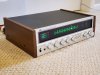
I did hook it up to some cheap speakers and it sounded fine. I will check out the rail voltages and may do some recapping in the near future. Someone said their DC offset went way down after replacing some caps on this thing.
 
Last edited:
I bought 50 with wire leads - i will use them down the road for other projects. LEDs might be OK, but it adds a bit of complexity to do it right on this receiver because of the way the bulbs switch and the AC inputs. I have lots of LEDs, but skipped it on this one. Check your grounds as i mentioned above in this thread and have fun with it. It will look great when it's done . . .

20220129_142105_resized.jpg
 
Last edited:
Hi VR-5505 folks. Newbie here. I am trying to re-lamp mine. I got the dial and Source/Out lights working fine. But I ran into issue with the Stereo indicator lamp.
I am using a 6V 20mA (if im reading the spec correct). The same ones I used for Source/Out lamps. (those working). The Stereo lamp does not even flicker, and i have a strong single. Any suggestion's would be greatly appreciated.

Thanks!
 
The stereo lamp is 6V 35mA. It's switched by X109 so check voltages around that transistor and diode test the transistor . . . Could be an alignment issue as well or some other faulty component in the lamp circuit or the MPX circuit.
 
There does seem to be power around it, I did not pull the transistor out but yet , it does seem to getting .5 to .6 on the ->|- setting on the dmm, and its consistent.
When you mentioned the 6V 35mA for the bulb, i double checked. The specs are ;

Volts; 6.3
Amps; .2 (+-10%)

Should that be .02 Amps? And could that cause the issue?

Thx

Chris

IMG_3279.jpeg
 
1789939619857.png

If you lamp is 6.3V, 0.2A then the circuit probably doesn't have enough current to light the lamp . . .
 
Yes, the supplier spec is stating 0.2 Amps.

Typical newbie mistake! Looking @ ebay seeing a LED at 6v 3mm, but not stating the draw. they have bigger ones that do 6V 20mA, and say it does both AC and DC. I will message them.

Do you think i should pull the bulbs from the source/output board? Think the spec was same @ 6V 35mA. I don't want to fry anything. I really like this receiver.

Thx again, for answering my novice questions!

Chris
 
Most LEDs will draw 15 ~ 20 mA so anything you use will work. This model uses a transistor to turn the light on, so using an LED will be OK. Many newer receivers use an HA1156 or similar MPX IC which is sensitive to current draw so using a correct voltage/current incandescent lamp is more critical in those applications.

If you put 200mA lamps on the source/output board, you should definitely change those out for more suitable lamps . . .
 
So I managed not to break the thing. I replaced all the 8V lamps with LED's. For the stereo indicator and tuner needle I used 3mm LEDs. I ended up using regular bulbs for the input/output selector lamps. And was able to source 6V 40mA bulbs. So I am not using the .2 amp bulbs I had in before. So one more nice little receiver survive!

JVC-VR-5505-ReLight.png
 
Beautiful. Glad you got it sorted out. Yours has some peeling on the lettering - mine did too. Must be common for this model . . .

20220129_142123_resized.jpg
 
Back
Top Bottom