• The move to the new server is done. There are some software and database maintenance updates in process. This has us passing the hat around to help out. We appreciate any donations. Seriously, even a dollar helps. The payment page may be found here - https://www.audiokarma.org/support.html

Candohm Resistors

kvflyer

Super Member
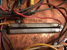
We sometimes see "Candohm" resistors in our audio equipment. They were used for years in TVs, radios and some Scott amplifiers (99C). They are usually a piece of resistance wire that has taps along the way. Often, they have as many as three sections. Each section will usually have a different wattage do to it's location in the circuit.

They are constructed with paper surrounding the resistance wire and clamped shut inside of a metal mounting. They are also mounted to the chassis to afford some heat sinking. Over the years, the paper often breaks down and the element can come in contact with the metal housing. Since the resistor is riveted to the chassis, it's at ground potential.

Back in the day, they served a good purpose. But today, they can cause some real headaches and parts destruction. An easy way to replace them is to install a terminal strip with discrete resistors of the correct value and wattage attached. But one must keep in mind that since the resistors are not "heat sinked", it will get hotter than expected... maybe.

Another approach is to use an aluminum resistor that is attached directly to the chassis.

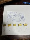
Some examples, I don't have a picture of a terminal strip with several resistors one it. But you can get the picture, I'm sure.

candohm.jpgCandohm2.jpgDaleReplacement.jpg

BTW, please feel free to comment or correct any of the above.
 
Register to hide this ad
The amp I was working on contained one, I think I changed it to discrete resisters correctly but unlike your pic I did not tie them to each other's I just lined them up and terminated to the loads with gaps between the line of resisters. But after it was said and done the power transformer shorted and at this point, I am not sure why. It was old, 1955 and I can't be sure if it was something that caused it or can the varnish on the windings short from just being so old and then put into use, and I don't know.

Needless to say I was very sad. :mad:
 
normally if you don't complete the circuit something doesn't get voltage and nothing especially bad happens other than it not working. Depends on the specifics I guess.
 
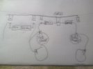
This is a diagram on how I configured it. Those tabs are the abandon terminals of the Candohm but I did keep the ground one as the drawings showed it as a ground and I checked the resistance and it was a direct ground.

Those tube sockets and the terminal were all on pin 8 and Gadget you indicated they were Cathode bias; the drawing shows each pin to have 20 volts.

WIN_20261004_12_56_43_Pro.jpg

Don't be too shy if I did something wrong let me know as I don't want to repeat a mistake. All along, that resister was the most troubling on that amp.
 
Last edited:
There are several ways to approach this situation. But whilst the Candohm resistor was great in its day (60 years ago) their "expiry date" has come and gone. I will admit that I should have replaced the one in my Admiral 26R12 Bakelite console television. I did not and was rewarded a few years later with quite a blue lightning show inside of the vintage "Admiral" labeled 5U4G tube. Needless to say, it rendered the tube kaput. For now, I mounted a terminal strip with a high wattage ceramic wirewound resistor. I do have a Dale aluminum finned resistor awaiting installation. That one can use the chassis as part of its heat sink.
 
There are several ways to approach this situation. But whilst the Candohm resistor was great in its day (60 years ago) their "expiry date" has come and gone. I will admit that I should have replaced the one in my Admiral 26R12 Bakelite console television. I did not and was rewarded a few years later with quite a blue lightning show inside of the vintage "Admiral" labeled 5U4G tube. Needless to say, it rendered the tube kaput. For now, I mounted a terminal strip with a high wattage ceramic wirewound resistor. I do have a Dale aluminum finned resistor awaiting installation. That one can use the chassis as part of its heat sink.

Did you see the drawing that illustrated the way I bypassed the Candohm in my RCA amp, and do you see an issue regarding how I did it?
 
Don't be too shy if I did something wrong let me know as I don't want to repeat a mistake. All along, that resister was the most troubling on that amp.
from a sanity POV that looks right. The most common one you see tends to be one long wirewound resistor with taps at various points. so it gets replaced with a chain of resistors. Its usually not individual sections with a center ground but obviously some are. Yours is basically 3 individual resistors, two of which happen to tie to ground so replacing it like you did makes sense.
 
Back
Top Bottom