genlabs
New Member
Hi all:
Full disclosure: I am no expert at this stuff. I have repaired my fair share of equipment but most of those repairs were straight forward, easy to find parts repairs. I am trying to learn at least one thing everyday.
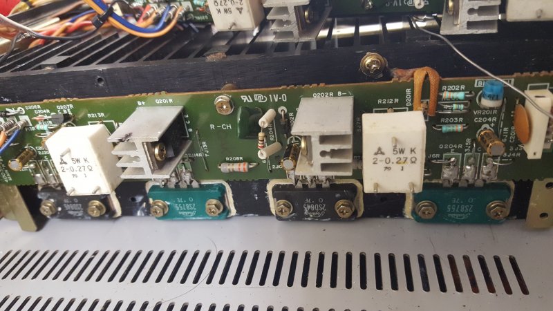
I am working on a SAE A202. I cannot bias this thing at all. The device plays but at low volume there are some artifacts. The heat sinks remain cold. I started Googling information about biasing diodes and blhagstrom pointed me in the directions of some mind blowing information on how members of this forum were constructing bias diodes from common diodes in a string. I thought "cool this is where I should start".
The bias diodes in this amp are super fragile so I did not want to remove them unless absolutely necessary.
If I measure across them in circuit, with my Fluke in diode mode, I read @ 1.63 volts.
If I measure voltage drop across them while the amp is powered up I read @ 1.9 volts.
I was really ramped up about building my own "homegrown" bias diode but after taking these measurements I think my bias diodes may be ok.
If I put my DMM across the emitter resistors of the two adjacent output transistors I read absolute zero. Turning the pot makes no difference. I have no documentation for this amp. I have done rudimentary checks across the few components on each amp module. The resistors have drifted a little but nothing dramatic. Any ideas or clues?
Full disclosure: I am no expert at this stuff. I have repaired my fair share of equipment but most of those repairs were straight forward, easy to find parts repairs. I am trying to learn at least one thing everyday.
I am working on a SAE A202. I cannot bias this thing at all. The device plays but at low volume there are some artifacts. The heat sinks remain cold. I started Googling information about biasing diodes and blhagstrom pointed me in the directions of some mind blowing information on how members of this forum were constructing bias diodes from common diodes in a string. I thought "cool this is where I should start".
The bias diodes in this amp are super fragile so I did not want to remove them unless absolutely necessary.
If I measure across them in circuit, with my Fluke in diode mode, I read @ 1.63 volts.
If I measure voltage drop across them while the amp is powered up I read @ 1.9 volts.
I was really ramped up about building my own "homegrown" bias diode but after taking these measurements I think my bias diodes may be ok.
If I put my DMM across the emitter resistors of the two adjacent output transistors I read absolute zero. Turning the pot makes no difference. I have no documentation for this amp. I have done rudimentary checks across the few components on each amp module. The resistors have drifted a little but nothing dramatic. Any ideas or clues?
Last edited: