
• The move to the new server is done. There are some software and database maintenance updates in process. This has us passing the hat around to help out. We appreciate any donations. Seriously, even a dollar helps. The payment page may be found here - https://www.audiokarma.org/support.html

Can't seem to find this Zener Diode....

QSilver

Super Member
I'm working on an SA-606 that has been kind of abused... It has been running at the wrong voltage which I think lead to the larger transformer (for the class B power amplifier) to burn out. I've replaced it with a 300VA Toroid that just managed to squeeze in.

Powering it back up, the amp doesn't seem to be coming on. It has a muting circuit that doesn't seem to be unmuting the amplifier. There is also a bit of a voltage sag on the supply for the meter lamps and LEDs. I should have around -7.5V being supplied to them and I'm only getting 3-4V. I went back to Q15 and I have -20V on the collector but only -5V on the base and emitter. I'm thinking that its D27 failing but I can't find any source on the internet for the part number SZ-027. Can anyone help me track this down or get a replacement?
 

Attachments
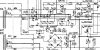
  • SA-606 power supply.jpg
    SA-606 power supply.jpg
    101.7 KB · Views: 61
Last edited:
Register to hide this ad
Check the circuit but it could be 27v Zener. You can add them up to make the value. Such as two in series; a 15v and a 12v will equal a 27v Zener.
 
See, I'm not 100% sure how this circuit is supposed to work. The zener diode is connected between the base of the transistor and the output to the filament bulbs. If the output to them is supposed to be ~7.5V then surely the zener would be more towards the 7.5V area of spec? But them the part number may hint at otherwise... so I'm confused... I haven't checked if its shorted yet... I can test that but I still need some sort of replacement... Can you help me understand what that zener is doing?
 
So I did some testing on the amp. I pulled Q15 to see if the voltages would balance out. The voltage on the collector went up to -46V which I think is ok seen as there is no load through those resistors. The Emitter was dead for obvious reasons and the base was sat at -7V which was closer but still not what it should be.

I then pulled the zener diode, and I did it in this order specifically to stop any problems caused from the lack of the zener damaging anything past Q15. Powered up with it removed and I get -11.7V where Q15's base should be. So thats much closer. I then realised that having pulled the zener, the amp was able to power up and switch on the base voltage to the first stages of the amp. So this zener is likely a trouble maker... question is now, what is it and what is the equivalent? The diode itself seems to say S-027 but maybe the Z is missing as the case is too small...
 
Leave it to avionic to know where the skeleton's are. I've been looking for it for 2 hours on internet.
 
Amazing! Thanks for that. Though, can you explain how the 27V zener is used to make a 7.5V supply? I guess its something to do with it being 27V and the supply being 20V.... but I'm not quite making the connection...

Maybe I'm wrong but wouldn't a 3W zener be quite big? The one I pulled was quite small...
 
Component size will vary from one manufacturer to another. The one I found at mouser is 2.7 mm dia. X 5.2 mm length.
 
Amazing! Thanks for that. Though, can you explain how the 27V zener is used to make a 7.5V supply? I guess its something to do with it being 27V and the supply being 20V.... but I'm not quite making the connection...

Maybe I'm wrong but wouldn't a 3W zener be quite big? The one I pulled was quite small...
looks like some voltages are written in a misleading way on the schematic . like in the wrong places . plus the zener is connected to a voltage divider .. wish i could explain it better why it drops to 7.5v for the lamps .. i think voltage might rise up with lamps removed though . and maybe thats why its there in case the lamps blow so the voltage doesn't rise too much .
 
Thanks for your replies. Parts are on the way. Amp seems to work just fine without these two at the moment though... just no lights!
 
I put the new zener diode in and refitted Q15 with some new heat paste. Bulbs are much brighter now and the amp continues to function when they're all connected up. The voltages on Q15 might need checking.. I'm still not sure if they're right. The schematic doesn't make to very clear.
C -11.5
E -4.5
B -7.2

Does this seem ok? There seems to be some heat coming from around R97 and D20...
 
Check for correct orientation of C69, 10µF 25V, C61? 22µF 16V, and C72, 33µF 25V.

I've done a visual check and all appear to be in correctly - I have done a re-cap on this unit so I will check against a schematic just in case there was an error on the silk screen. I've also noticed R100, R101 and R123 get incredibly hot - I could smell the dust burning off them and I couldn't touch them after having it on for a few minutes...
 
correct lamps fitted ?
d27 correct way round ?
seems like far too much current is being pulled for some reason
is the power led lighting up properly ?
 
I used a BZT03C27 for the 27V zener. I installed it with the black stripe matching the side of the symbol on the board with the black line across the symbol if that makes sense which I think is correct....

The power LED is good and the bulbs are ok too. Perhaps it is a problem with the filament bulbs... I think I have put it 8V 100ma as opposed to what the schematic calls for which is 8V 55ma... :yikes:

I could try running it without these two filament bulbs?
 
Last edited:
Removed one lamp and tried again. Much better. I have -20V on the collector and -7.5 on the wire to the bulbs. I'm not sure if its quite happy though...
E: -8.4
C: -20
B: -9.5

Having just re-looked at the schematic... I think I see your point more clearly about the voltages being written in bad places. Maybe this is ok now... and I just need to get the correct bulb. That collection of resistors still does get too hot to touch but now I don't smell the burning... though I find their placement next to the main electrolytics a bit of a design flaw...

I was looking at some more axial bulbs but seems the closest I can find is a 55mA bulb rated for 10 to 15V... would that be okay or is it still out of the park a bit too much?
 
Is there anywhere in the UK to source them? I'm having difficulty. Otherwise I'll ask David Wojnarowski about them...
 
Back
Top Bottom