
• The move to the new server is done. There are some software and database maintenance updates in process. This has us passing the hat around to help out. We appreciate any donations. Seriously, even a dollar helps. The payment page may be found here - https://www.audiokarma.org/support.html

Capacitor -/+ placement Power supply board

Maddart

Active Member
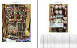
I am recapping a PS board and am concerned about the neg placement on the pcb. obviously i just want to replicate what i am removing. looking at the foil side the polarization doesn't seem right. C12 and C13 are of concern. This is a project one mark ivb and there ia absolutely no documentation available. I am hoping someone else can see what i am not seeing.PS PCB.jpg
 
Register to hide this ad
Think i just answered my own question. The side that C12/C13 are on is the negative voltage side. Now it makes sense
 
If it's a (+)-G-(-) power supply then just have to keep in mind the caps for the positive rail will have their negative terminals to common/ground and the negative rail caps will have their positive terminals to common/ground.

That's what it looks like to me is going on.
 
Many a recap has gone wrong by switching the polarity of the negative rail power supply caps!
Put the new ones in the same way as the old ones came out. It takes some thinking to see that the positive side going to ground is correct and is still more “positive “ than the negative side.
 
You have a picture of the board before your intervention. Just fit everything as in that picture, double check against the picture after finished, and that's all.
 
yeah looks correct to me for a split rail supply. "ground" is just the 0 volt point, one supply rail is positive, the other is negative so one cap is - to ground, the other is + to ground.

the original caps not being blown up is another confirmation that its correct.
 
Back
Top Bottom