• The move to the new server is done. There are some software and database maintenance updates in process. This has us passing the hat around to help out. We appreciate any donations. Seriously, even a dollar helps. The payment page may be found here - https://www.audiokarma.org/support.html

Capacitor:Ripple current rating, how high is needed?

GrisPato

Super Member
I spend most of my time on the "Sansui Exclusive" forum. I also scroll past the new messages frequently and lately notice a lot of comments about ripple current when members advice other members about choosing capacitors.
Often the advice is : the one with the highest ripple current!
First, I get the impression, when it is said that way, people think it is a "current amount the capacitor can deliver" parameter. But it is a rating of how high a ripple current the capacitor can endure, consistently at the temperature rating and life expectancy.
Second, how do you calculate the maximum ripple current a capacitor will see in a certain amplifier?
The only thing I can find is on the site of Rod Elliot, Sound.au, where he says 2 X the maximum current your amplifier can deliver.
This would mean with a power amplifier of 100 W@8ohm/150 W@4ohm /channel at a rail voltage of 45 V at maximum power, 2,5-3,5 A x 2 = 5-7 A/ channel.
This would mean that the life expectancy if you would run a signal that would output maximum power continuously ( impossible playing music ) @ rated temperature ( what is not common but can be) is doubled. When the temperature is 10° C lower it will double again, etc.
Even more interesting is it for the local decoupling capacitors on the PCB. They often see practically now ripple current. Can I say, in the mA. So how would it matter for choosing a capacitor if the ripple current rating is, let's say a 470uF-63V capacitor, 800 mA or 1300 mA. Do you have to use this for the filtering of rectified AC for a pre amp? Yes, there it matters, for local decoupling I would say not.

Does this make sense?
Do I see this wrong?
What am I missing?

I would love to hear people's opinions!
 
Register to hide this ad
I spend most of my time on the "Sansui Exclusive" forum.
greetings and welcome to the diy side of the forum. its been a while since my disruptive post in the sansui realm about the au-717 and au-719. hopefully your are in good health, both mental and physical.

capacitors in general seem to be a moving target although power filter caps are fairly easy to run simulations depending on circuit load. for linear supply design on vintage gear it helps to bump up the value more often than not, youtube xraytonyb has some good info and test results about the topic. calculating an optimal value vs minimum value (humans will perceive as insufficient) has yet to be defined i.e. how much ripple on the rails is needed before the listener hears an issue not related to personal preference.

*calc near bottom of page

Often the advice is : the one with the highest ripple current!
highest ripple rating and highest capacitance until the rectifier diode(s) burn up due to cold start inrush current. and then the rabbit hole of a soft start circuit plus other "weakest link" design mods.

But it is a rating of how high a ripple current the capacitor can endure, consistently at the temperature rating and life expectancy.
correct, although ability and life expectancy are derated when the component is stressed above 25c temp and other factors stated in the caps spec sheet.

So how would it matter for choosing a capacitor if the ripple current rating is, let's say a 470uF-63V capacitor, 800 mA or 1300 mA. Do you have to use this for the filtering of rectified AC for a pre amp? Yes, there it matters, for local decoupling I would say not.
oddly enough higher capacitance reduces overall ripple, naturally, so a high capacitance with medium or low ripple rating should be fine for a power supply. going from 470uf to 1000uf would improve filtering even if ripple rating is 1000ma (470uf) vs 600ma (1000uf) as a random numbers example.

seems like cap esr is part of the ripple calc once the system is at steady state, cap charge time constant would not be of significance (tau) unless rate of recovery is of concern.


LTspice sim or the falstad circuit sim might help dial in a value or at what point more becomes less (more capacitance vs less financial savings). component physical size tends to be a constraint as well for power filter caps. using a capacitance multiplier circuit could help for the down stream rails/circuits.

This would mean with a power amplifier of 100 W@8ohm/150 W@4ohm /channel at a rail voltage of 45 V at maximum power, 2,5-3,5 A x 2 = 5-7 A/ channel.
if its 45v+45v rail to rail which would be around 42+42 usable, the numbers might be 100w rms / 84v = 1.19a per channel (0.6a per rail) plus overall circuit losses.


*for humans addicted to math

since amplifier output ratings are tested at 1khz the overall load might be less, further testing and measured data needed.
 
If someone is constantly pushing their amp close to max output its time to get a more powerful amp. Changing to a filter cap with higher current rating isnt gonna fix the bottlenecks it sees in the amp circuit. The ripple current ratings are mostly dictated by capacitance and voltage.

I was just ordering filter caps for a 50watt amp and it was designed properly with 10000uf 50v caps, I ordered some 10000uf 63v caps rated at 6.5amp but that is plenty for a 50watt. Looking at the ripple current of 10000uf 63v they are rated from 4.4amp to 10.2amp which wouldnt fit in my amp anyway because it needed a 4pin with 22mm spacing so that was the deciding factor for me and the 4 pin caps were rated from 4.5amp to 6.5amp, either of which has more than enough current handling for that amp as they only see half the current.
 
Example of ripple current rating in a specification.
From what I can find Epcos/TDK give most information. I am going to assume this counts for most filter capacitors.

Screenshot_20250224-004311.png

What you can see is that the ripple current rating goes up 300 % for the difference in temp.
All the amplifiers I own have a temp much closer to the 40°C then to 85°C.
 
Ripple current causes capacitors to generate heat, which can increase their temperature and shorten their lifetime
Yes, but how much life time do you need?
The last thread where the advice: " take the one with the highest ripple current" all suggestions had a ripple current rating of minimum 12 A @ 85-105°C for a receiver with an output of 120w@8ohm/channel. So even the capacitor with the lowest rating will last around 20-30 years, all other things considered.
So why choose a capacitor that lasts 50 years.
 
I wouldnt over think it too much. Time alone just sitting on a shelf dries out electrolyte so 50 years isnt a reality unless hermetically sealed. If your amp was designed after 1975 most any filter cap the same capacitance and voltage will be adequate unless it was an entry level amp, just stay away from cheapo caps and go up to the next voltage or value for a bump in ripple current handling ability. If the amp still doesnt have enough umph then get a amp rated for more power.
 
I wouldnt over think it too much. Time alone just sitting on a shelf dries out electrolyte so 50 years isnt a reality unless hermetically sealed. If your amp was designed after 1975 most any filter cap the same capacitance and voltage will be adequate unless it was an entry level amp, just stay away from cheapo caps and go up to the next voltage or value for a bump in ripple current handling ability. If the amp still doesnt have enough umph then get a amp rated for more power.

I am not over thinking, I just wanted to know if I am missing some information, reading people advicing and using the ripple current parameter as if it is the most deciding factor. Not that i think it is a deciding factor except maybe when al else is equal. It is important in the way that you do not want a capacitor that has a low ripple current rating if they exist even. And it becomes really important in any class A amplifier where the bias current is consistently several Ampere.
In a normally used class AB amplifier playing average music program, the ripple current will not reach the rated current for probably 90-95 % of the time.
There is not a maximum current limited by the rating. If the capacitor would have to deliver several times the current it is rated for it will happily do it assuming the capacitance is sufficient.
Like you mention in the last sentence of your comment, a higher ripple current rating is not going to give you more power at all!
 
although ability and life expectancy are derated when the component is stressed above 25c temp and other factors stated in the caps spec sheet.
Interesting, because what i read in specification that life expectancy is given for example xxxxHours, xxA ripple at xxxTemp, where Hours are doubled for each 10°C under rated temp, and ripple current is Xx larger for lower temp ( see example specsheet Epcos )
 
I chose the one I did because their Leakage was .006 CV and it was rated for 15,000 hrs at 85C. The higher amp rating was just a side note with that particular purchase because the amp isnt a particularly high amp circuit. When comparing Leakage be sure to compare apples to apples as some manufacturers show after 1min, 3min or 5mins, it should be lower the longer the time.

It was kind of no brainer because the Kemet I got had lower leakage, 7x's the rated life and a higher ripple current rating than the other one they had in stock and prices were very similar.

I once had a 20watt receiver on the bench and while the filter caps were out tried 4 different filter caps by jumping them in with thick lead alligator clips. The screw caps I was excited to try werent any better than the smaller sized ones with the lower current ratings. Most circuit designers of audio gear already have figured out most of the stuff for us and chose the right sized parts, sometimes cost prevented them from using the more robost parts but I dont expect miracles by uprating filter caps any longer.
 
Last edited:
Do you mean with this that ripple current rating is the determining factor after capacity?
cap specification priorities based on usage, type of circuit and load within a particular environment. like dialing in a transistor alternative when updating/upgrading a specific circuit.

for a power supply with 45v rails it would be normal to see a stock cap with 50v rating, some safety breathing room if the mains goes up a couple volts. a power supply cap also needs a suitable size capacitance or the ripple will cause too much self heating plus allow too much noise in the downstream circuits.

if the stock value is [4700uf 50v 85c] for a power amp hopefully the manufacturer used a cap with a suitable ripple current rating since it is a feature that will be utilized. chances are most vintage gear are woefully lacking in regards to cap specification (50's/60's/70's/80's).

*upgrading to 63v : adds a larger safety buffer vs mains voltage fluctuations and also increases capacitor service life by a small amount.

*upgrading to 6200uf : will improve noise filtering and energy reserve plus have a higher ripple current rating (as a side-effect).

*upgrading to 105c/125c/135c : will improve longevity especially if in a hot environment, certain chemistries might improve other abilities as well.

*upgrading to a higher ripple current rating : depends on what the original components rating was in order to know if an upgrade is possible and if so by how much. overall, improved lifespan more tolerant to heat generation.

*upgrading to low esr :
Screenshot 2025-02-23 at 22-12-15 Why Low ESR Matters in Capacitor Design.png

from a repair enthusiasts point of view upgrading all the above parameters can be done and without breaking the budget. so it becomes a somewhat moot point as to which parameter is first to consider and then 2nd/3rd/4th/...

physical size limits how far a person can go with voltage and capacitance ratings, there is a ceiling.

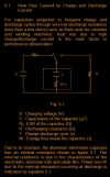
Screenshot 2025-02-23 at 22-17-31 TECHNICAL NOTES FOR ELECTROLYTIC CAPACITOR - charge-discharg...png
from a rubycon pdf: charge-discharge-data.pdf

Yes, but how much life time do you need?
as much as possible is not a bad thing, overkill spec's on the newer component generations are not a bad thing. shopping for carbon comp resistors to replace the 1960's / 1970's original is just cruel, as a comparison to resistor technology upgrades (film, oxide).

reading people advicing and using the ripple current parameter as if it is the most deciding factor.
it is a parameter of significance, more than usual if shopping for power supply caps. some posts can get a bit crazy with "the one and only top parameter to shop for" type of dialog.

 
i read in specification that life expectancy is given for example xxxxHours, xxA ripple at xxxTemp, where Hours are doubled for each 10°C under rated temp, and ripple current is Xx larger for lower temp
the 1000/2000/5000/10000 hour ratings are a lab tested guarantee that the manufacturer can specify and anything beyond that testing environment spec is unknown. cap will still function reasonably well but who knows for how much longer, hour/day/week/month/year/decade/century although definitely not a millennia.

1000 hours at 85c and then double for every 10c below that temp, is correct and accurate. as temp goes down lifespan goes up. just like if temp goes up lifespan goes down which is how i worded things due to transistor and resistor lifespan analysis. i should have worded things differently in hindsight, my error.

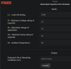
the calc link above, eepower.com, helps with the cap thermal math.

Screenshot 2025-02-23 at 22-50-13 Electrolytic Capacitor Life Calculator - Power Electronics C...png

unfortunately heat is not the only aging factor of an electrolytic, thats where the equations get complicated.

the joys of newer generation components is that they will last longer than the originals did, if the manufacturer got things right.
 
Not sure I agree with that first link in post #2, is it suggesting that ripple current is somehow tied to some residual component from rectification or...
And the calculator has no mention of load/class A or...

My basic understanding is,
- a diode bridge will give you fullwave rectification at twice mains frequency, 100/120Hz (below, looking at +ve rail only)
ie, a diode bridge/pair does not give you dc
- a smoothing cap is used to store the energy from this waveform
if the capacitor was ideal, that is no leakage and.... and there was no load connected then the voltage waveform would be pure dc, ie, the cap would charge up and hold its charge.

But in the real world there is a small amount of leakage but things like bias currents (both pre/power amp) that consume energy that during the troughs of the fullwave, draw energy from the caps so the voltage drops, later the cap is recharged by the next "pulse" and the voltage rises, this cycle of discharging then charging is the ripple

As we crank up the volume we need more power from the caps (during troughs of fullwave), so the voltage drops further giving higher ripple

The yamaha CA-1000 (CA-1010, CA-2010) operations switch provides selection between Normal(AB) and Class A
Measurement of p-p ripple at idle at main caps gives about 50mV (AB) and about 1V(Class A), point is it's the load (amplifier) that causes the ripple not the rectification process.

The OP's question on calculation of needed ripple rating is a good one and will need some thought however a link to maximum power consumption appears reasonable.
 

Attachments

  • fullwave.png
    fullwave.png
    8.8 KB · Views: 0
Using google,

for voltage use rails voltage
for current, bit more difficult either use SQRT(max power/8ohms)?
result is a ripple voltage, convert to ripple current using esr???
more questions than answers...
 
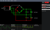
after running a simple yet effective sim on falstad it would appear that ripple is a two edged sword for circuit design.

Screenshot 2025-02-23 at 19-21-53 Circuit Simulator Applet.png
tinyurl.com/2czwap6l for anyone interested in exploring my crude attempt at a simulation

double click on components to edit values, simple interface even for those unfamiliar with the site. feel free to explore the other sims on this devs site, lots of fun stuff like visualizing room modes.

circuit using 120v rms 60hz for mains, txf ratio adjusted for +/- 45v dc output.

Screenshot 2025-02-24 at 12-33-50  falstad sim ripple-1.png
sword edge #1: loading of the circuit (1000uf 50r). decent sized filter cap vs low resistance load.

load simulating close to speaker impedance since output transistors are a load regulator i.e. input signal level (audio) controls what percentage of the output current will flow.

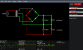
Screenshot 2025-02-24 at 12-39-20  falstad sim ripple-2.png
1000uf 500r, decent sized cap high resistance load

possible example of no load idle of the amp or at least reduced stress on the power supply. output resistor scope is dc coupled view, filter cap is ac coupled view to focus on ripple magnitude.

Screenshot 2025-02-24 at 12-44-39  falstad sim ripple-3.png
sword edge #2: filter cap design size (too small from the factory) 100uf 500r

high resistance load with an under sized filter cap.

Screenshot 2025-02-24 at 13-03-33  falstad sim ripple-4 .png
100uf 50r, under sized filter cap with low resistance load (high stress/ripple)

i wonder how bad the sound will be with a similar under sized filter cap scenario? for example a vintage receiver with a manufacturer trying to reduce costs without sabotaging the end product. youtube xraytonyb vid covers this scenario much to his surprise.

Screenshot 2025-02-24 at 13-23-16 Increasing the Main Filter Cap in an Amplifier - What Happen...png
youtube.com/watch?v=47aDmfMwpCw
*his moment of surprise at 15:04 timestamp

how much ripple is needed to become audible to the average human with average hearing range, that is another question requiring a threshold value for point of reference. since an amp stage needs energy storage for dynamic output and clean filtered dc to create clean output (regardless of speaker quality) it appears that "higher is better" should be considered for updating stock cap sizes. too high leads to exposing other weak links in the circuit which can be adjusted as well.

if filter cap size is the bare minimum to achieve the 1khz wattage rating on a products spec sheet, it is most certainly too small for quality performance for 20-20k hz performance since bass spectrum needs higher than average energy reserve.

so much vintage gear could sound noticeably better by bumping up the stock filter cap values (main power supply and sub-circuit local filters/storage. reducing hot spot locations is another design mod most vintage gear need as well, thermal camera helps significantly.

hopefully this long winded post isnt too far off topic. just demonstrating an rc charge circuit with variable load.
 
Lots of vintage equipment had power filter caps with averaged ripple current specs in the 2-4A range (maybe). Lots of newer replacements we put in have higher capacitance and higher ripple current ratings, which is also fine (sometimes an improvement esp. w/ the added capacitance). The higher the ripple current rating, it appears the caps operate a bit cooler which is nice, helps lifetime, and is another added benefit of increasing that figure. Another thing I noticed is that newer power caps generally have pretty high ripple ratings (compared to vintage OEM it seems). If you increase the ripple current ratings several amps more than original, what I've noticed is that the music sounds more impactful and impressive on lower, normal listening volumes. The downside is that at a higher volume, it seems the music gets a bit more over-emphasized, edgy, congested or shouty earlier on in the volume dial. Use Digikey's parametric search function. They list ripple current ratings at both LF and HF for power filter caps. Look at both of these figures when choosing caps, not just one averaged ripple current figure. I found that competitively listed LF ripple (but not competitively listed HF ripple) may lead to a better tonal balance of the music from low to high. There are exceptions to this, as some "audio-rated" caps have competitively listed current at HF (as well) and can still sound pretty good at higher volumes. My ears seems to be more sensitive to additional HF current compared to LF current it seems. More LF current just seems to fill-in the music a bit more in the lower registers usually leading to more satisfying or fuller bass presence -further reducing the need for a sub.

However, generally speaking, I've not increased current ratings more than a couple amps over stock and this seems to maintain the original tonal balance of the sound a little better. This LF/HF current "spread" contributes to either an under-emphasis, neutrality, or over-emphasis to the sound at both LF and HF. Those are the three options for both frequency extremes. The reason I know too much current at HF can be bad, is that the treble will consistently hurt my ears (more) at a louder volume compared to before the recap with caps that didn't have as high of a current rating at HF to begin with. My ears are very sensitive to listening fatigue and sibilance with treble at higher volumes with too much HF current. Sometimes I have to turn down the music (where I didn't have to before at the same volume level). I've let that be my guide in power cap selection and it has given me the results I am looking for, which is to say something that still sounds good and holds together tonality/ emphasis-wise at higher volumes without hurting my ears as much.
 
Last edited:
Nice post!
And exactly what I have a problem with. Ripple current rating is just that. The amount of ripple current a capacitor can handle at a certain temperature (rated at 85°/105° most commonly) for a certain time.
This would depend on the ESR value, how well the capacitor can dissipate heat and hold on to its electrolyte. So, over time (normally a time much longer then the expected use) it will perform better to spec.
It should not say anything about the sound, frequency response, etc.
 
Back
Top Bottom