• The move to the new server is done. There are some software and database maintenance updates in process. This has us passing the hat around to help out. We appreciate any donations. Seriously, even a dollar helps. The payment page may be found here - https://www.audiokarma.org/support.html

Carlson-Stromberg ASR-333 modified - by-pass Tone Controls

ngoyette

AK Subscriber
Subscriber
I have modified my ASR-333 to be just a power amp by-passing the Tone Control circuit (see attached schematic) . I also elevated the heaters to 25 Vdc
The Master Loudness is still in the circuit, I keep it at max volume.

The amp sounds great, I am very happy with the performance, however, the maximum input signal is 0.4 VRMS, if I go to 0.41 vrms, it starts to distort right away.
The other amps I have usually have around 0.9 vrms before there is any distortion.

Is there a way to adjust the input sensitivity on the 6U8A?
 

Attachments

Register to hide this ad
Just a curious question not related to the gain:
What do you use for a pre-amp?
I use the front end of a Marantz 1060.
 
Good idea, I don't know why i did not think of that myself
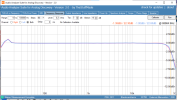
Hi Gadget, I tried what you suggested and it works out in some areas, but the frequency response is not good.
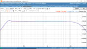
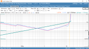
Below is without attenuation and below that is with the attenuation.

Maxed out volume:

ASR-333-Non-Attn-sig-Freq-Rsp.png

Adjusted volume:

ASR-333-Attn-sig-Freq-Rsp.png
 
yea I was wondering if that might be a problem. You're seeing the Miller effect in action, large resistance of the pot working into the capacitence of the tube causes the HF roll-off. The bump at the low end is probably the loudness compensation parts attached to the tap.

LF bump is easy, unhook C16 and C29, the caps that are connected to the side tap on the gain pot. HF roll-off is minorly more difficult, but a small cap from the "top" of the pot to the side tap will likely do it. Exact value will depend where you have the control set and probably needs a bit of experimenting to arrive at.

Other option is to bypass the gain pot entirely, install a fixed voltage divider, and bypass the resistor between input and grid with a small value cap to flatten out the response. Electrically thats the same, but you can do it with smaller value resistors which means less Miller effect in the first place. I'd probably go with maybe 100K total from input to ground, divided up wherever you need it to. If you want about 0.9v and it currently won't allow more than 0.4, a 56K from source to grid and a 47K from grid to ground ought to get you pretty close.
 
The other-other option gets more complex. You'd need to figure out how much negative feedback is currently employed. Easiest way is to unhook the 100K feedback resistor from the speaker secondary, set the output to some easily-measured level, then re-connect the resistor and note that voltage. 20log (V1/V2) = dB of feedback. Note for future reference.

then you have to reduce the open loop gain of the amp. I'd probably try shrinking the plate resistor on the 6U8 pentode first. Get that where you want it, then re-connect the feedback and adjust the feedback resistor until the original feedback level is restored.

another way, re-wire the 6AV6 stage to be a cathode follower. That gives ballpark 0.9x the output voltage as whats fed into the grid. More importantly its basically immune to Miller problems. Put that between the gain pot and the grid of the 6U8 pentode. There is some signal loss, but without the Miller problem and with the loudness parts unhooked it will allow you to dial in the gain where you want and not have much trouble with HF loss.
 
Try that at a lower output level, maybe 1 volt peak to peak, just to make sure you aren't running into any power bandwidth limitations before making too many determinations here.

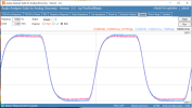
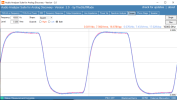
Thats not awful though, no ringing, no overshoot, that tends to imply a very stable amplifier though maybe with a little bit more bandwidth limiting than you might want. Tweaking R39 and/or C31 and its equivalent on the other side will sharpen that up, just be careful to not get it unstable. Smaller cap / larger resistor will move the roll-off point upwards and sharpen the square wave.
 
Try that at a lower output level, maybe 1 volt peak to peak, just to make sure you aren't running into any power bandwidth limitations before making too many determinations here.

Thats not awful though, no ringing, no overshoot, that tends to imply a very stable amplifier though maybe with a little bit more bandwidth limiting than you might want. Tweaking R39 and/or C31 and its equivalent on the other side will sharpen that up, just be careful to not get it unstable. Smaller cap / larger resistor will move the roll-off point upwards and sharpen the square wave.
The input signal was 0.2 Vrms so it should not be running into any power bandwidth issues. Once I correct the input signal issue I will work on the feedback tuning, thanks for all your support.
 
It may not show anything, just want to be sure there is no overshoot thats being clipped off by the higher level. If its still the same basic shape you're good to go. Tweak the low pass stuff until it squares up without also becoming unstable.
 
I implemented the Voltage divider circuit, without the cap yet.
The max input signal at 1khz is now 0.82Vrms, which is great.
However, when I run a 10k sine wave, if I go over 0.7Vrms, the signal distorts.

Do you think this is anything to be concerned about?

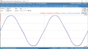
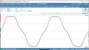
Below are the results of 10k sine wave at 0.7, 0.8 and 0.9 Vrms.

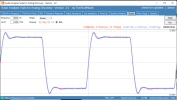
At the bottom is the 10k square wave at 0.2 Vrms (which I think looks good)


10k_Sinewave-0.7vrms.png
10k_Sinewave-0.8vrms.png

10k_Sinewave-0.9vrms.png

10K square wave:

10k-Sqr-Wave.png
 
30.5v p-p is 10.79 RMS, into 8 ohms thats 14.5 watts which realistically is about all these are capable of. Looks like the top is clipping at the same point its developing crossover distortion. You may be able to squeeze a bit more with EFB to keep the bias from drifting but I wouldn't expect a massive improvement.
 
You could also try the zener diode scheme on the EL84 cathodes as @gadget73 suggested to me recently for another project. It works and I go about 2 additional clean watts before clipping with no visible crossover distortion.
 
Back
Top Bottom