


ClickyButton
New Member
Hello! I'm new to audiokarma, so I apologize if this is in the wrong section. I wasn't sure if I should post it here or on DIY, so I guessed. Admin, please feel free to move it if I messed up.
I am restoring a Sony linear tracking turntable I picked up for cheap. The platter and linear tracking worked fine, but (1) the sensor to detect a 7" record didn't seem to work (despite the rubber mat being lined up with the holes) and (2) only a hum came from the phono out.
I figured out problem 1 fairly quickly; the photosensor worked but was angled specifically to detect light from the turntable lamp, which was burnt out. I could make it work by aiming a flashlight just right. It took more disassembly than I expected to get the bulb replaced, but I got it done.
Problem (2) didn't concern me at first. This turntable had been sitting a while and I assumed it was a bad cartridge. But while I was digging into the unit, I figured I should check the 4 conductors going from the tonearm to the phono rca plugs.
I confirmed continuity where it should be for a P type cartridge (with the cartridge removed, of course). Red and White had continuity to their respective RCA jack center conductors, blue had continuity with the outer white conductor, and green had continuity with the outer red conductor. So far so good.
But then I realized there was similar continuity (on the order of single digit ohms) between the outer and inner conductors of each RCA cable. Sure enough, the green wire had continuity with the inner red conductor, the red wire had continuity with the outer red conductor, the white wire had continuity with the outer white conductor, and the blue wire had continuity with the inner white conductor.
I assumed this was a short circuit, and figured the most likely culprit were the male RCA jacks themselves, as they were slightly out of round when I got them and I had to straighten them out. So I replaced them with high quality solder-on Jacks.
But there is still cross-continuity between the blue and white wires and the red and green wires.
Inside the unit, the 4 conductors come down from the tonearm and go directly to a PCB near the back of the case. The wires that go to the RCA Jacks go to this PCB too, and the PCB simply serves as a location to solder the 4 tonearm conductors to the 4 RCA conductors together in such a way that you can't damage the delicate tonearm conductors by yanking on the RCA wires. The solder joints look good and do not appear to touch.
I figure now I need to start cutting things off: the Jacks (again) to make sure it's not a problem with them, then the wires from the PCB. If it's on the PCB, I can bypass it. If it's up the tonearm wire, I'm not sure.
BUT- Before I do anything, I want to make sure I'm not chasing a wild goose. It seems unconscionable to me that there should be continuity between the inner and outer parts of the RCA jack, but I'm really only familiar with DC, AC power, and digital wiring, not AC circuits and audio. The fact that both coax wires have continuity with themselves but not at all with each other has me worried that maybe my assumption is wrong.
Am I correct in assuming there should be no continuity (should be open loop) between any of the conductors when there is no cartridge installed?
Does anyone have any troubleshooting tips for me?
Thank you!
I am restoring a Sony linear tracking turntable I picked up for cheap. The platter and linear tracking worked fine, but (1) the sensor to detect a 7" record didn't seem to work (despite the rubber mat being lined up with the holes) and (2) only a hum came from the phono out.
I figured out problem 1 fairly quickly; the photosensor worked but was angled specifically to detect light from the turntable lamp, which was burnt out. I could make it work by aiming a flashlight just right. It took more disassembly than I expected to get the bulb replaced, but I got it done.
Problem (2) didn't concern me at first. This turntable had been sitting a while and I assumed it was a bad cartridge. But while I was digging into the unit, I figured I should check the 4 conductors going from the tonearm to the phono rca plugs.
I confirmed continuity where it should be for a P type cartridge (with the cartridge removed, of course). Red and White had continuity to their respective RCA jack center conductors, blue had continuity with the outer white conductor, and green had continuity with the outer red conductor. So far so good.
But then I realized there was similar continuity (on the order of single digit ohms) between the outer and inner conductors of each RCA cable. Sure enough, the green wire had continuity with the inner red conductor, the red wire had continuity with the outer red conductor, the white wire had continuity with the outer white conductor, and the blue wire had continuity with the inner white conductor.
I assumed this was a short circuit, and figured the most likely culprit were the male RCA jacks themselves, as they were slightly out of round when I got them and I had to straighten them out. So I replaced them with high quality solder-on Jacks.
But there is still cross-continuity between the blue and white wires and the red and green wires.
Inside the unit, the 4 conductors come down from the tonearm and go directly to a PCB near the back of the case. The wires that go to the RCA Jacks go to this PCB too, and the PCB simply serves as a location to solder the 4 tonearm conductors to the 4 RCA conductors together in such a way that you can't damage the delicate tonearm conductors by yanking on the RCA wires. The solder joints look good and do not appear to touch.
I figure now I need to start cutting things off: the Jacks (again) to make sure it's not a problem with them, then the wires from the PCB. If it's on the PCB, I can bypass it. If it's up the tonearm wire, I'm not sure.
BUT- Before I do anything, I want to make sure I'm not chasing a wild goose. It seems unconscionable to me that there should be continuity between the inner and outer parts of the RCA jack, but I'm really only familiar with DC, AC power, and digital wiring, not AC circuits and audio. The fact that both coax wires have continuity with themselves but not at all with each other has me worried that maybe my assumption is wrong.
Am I correct in assuming there should be no continuity (should be open loop) between any of the conductors when there is no cartridge installed?
Does anyone have any troubleshooting tips for me?
Thank you!


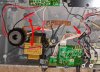
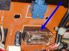

 . Follow purple'ish arrow and reference with original picture (my copy is more blurry)