kerozene said:
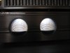
Rich, I have a TFM-75 with the lights still working but from what I hear they will fail, could you post a sketch/schematic for the mod you performed to your Carver?
And yes, I can shake the whole building from the foundations with this thing...

Toni
The unit I modified was a TFM-35x. It is currently installed as the power amp for my congregation's sound system. The mod was so electrically simple, that if I did draw a schematic, it probably was on a scrap of paper, which I kept only long enough to complete the job. It is really inconvenient for me to try to open up the unit to refresh my memory.
Essentially, what you need, is a resistor in series with the LED. It is possible that the original meter lamps (2) were in series, and were supplied with a DC voltage. If I recall, the lamp board, actually had a pair of pads available to install the resistor, with a jumper installed.
The positive supply voltage goes to the top of the resistor. The bottom of the resistor is tied to the anode (+) of the LED. If the two lamps are in series, the cathode (-) of the top LED is tied to the anode (+) of the bottom LED, and the cathode (-) of the bottom LED is tied to the lamp supply return (-). If the lamps are not in series, the cathode (-) of the single LED is tied to the lamp supply return (-), and you will need a duplicate circuit for the second LED (resister and LED), tied to the lamp supply in the same way (parallel connection).
Now, if the lamp supply is A/C, you will need to put a steering diode across each LED (cathode to anode). This is so the LED is not reverse biased more than a volt or so, during the negative half-cycle (current will flow through the diode). LEDs don't like to be reverse biased. To pick the resistor value, subtact the on-state LED voltage (if in series, 2x LED voltage), at the recommended forward current (typically around 2v per LED) from the lamp supply voltage, and pick the resistor value so the the remaining voltage is dropped across it at the desired forward current: R (in ohms) = remaining voltage (in V) / forwardCurrent (in amps)
The resistor power rating should be at least twice the power dissipated by the resistor: P (in watts) = forwardCurrent * forwardCurrent * R
I'm not is a position to draw the circuit, but maybe another can do it.
You will need to orient the LEDs so that they do not shine directly into the meters, cause the illumination will not look good. Instead, aim the LEDs into white reflectors, that bounce the light into the meters. That way the light will more evenly illuminate the meters.
I hope I haven't confused you too much.
Rich P