• The move to the new server is done. There are some software and database maintenance updates in process. This has us passing the hat around to help out. We appreciate any donations. Seriously, even a dollar helps. The payment page may be found here - https://www.audiokarma.org/support.html

Carver M-200t idle current high

rfitts46

Active Member
Have a Carver m-200t on the bench.
Acquired with no fuse/no fuse cap. The triac was shorted mt1 to mt2.
Triac replaced with littlefuse Q4015L5.
Powers on but idling with 2A with 55V rail adjusted down to 35V. Adjusted to 55V amperage climbs to 4A.
The mag coil T2 gets hot quickly within 5 minutes.
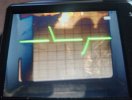
Triac firing looks off.
The 12V, 25V, and 55V rails are not drawing high current.
I started a thread on the carver site but it was locked not allowing any more posts.
I was told I was going to start the amp on fire?
thecarversite.com/topic/26976-m-200t-transformer-gets-warm

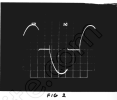
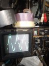
The oscope image of triac mt2 looks like the triac is conducting when it should be off and not conducting when it should be?

Need advice on determining if the triac control circuit is functioning properly?
May be a bad transformer?20240711_192928_copy_1337x1013.jpg
 
Last edited:
Register to hide this ad
Is the mag coil really ok? If its getting hot, its shot. Common problem with the Carver amps of this era was magneto restriction. Probably why triac firing bad and dc issue. I am sure the smarter folks will be on to help. I chimed in because I had a M1.5T same symptoms and mag coil was shot. Insulation was shedding a bit also from the heat. If its shed its dead, no way to fix except a new mag coil
 
Northwinds thanks for the reply. Yes it's a definite possibility. But if indeed the trigger circuit is driving it incorrectly could heat up as well.....
 
Measured the Diac breakover voltage Vbo in circuit.
Using variac the VAC is increased until the diac conducts.

Fluke measures 56Vrms(160Vp-p) or 80Vp.
Oscope confirms this.
Am I doing something wrong?
Expecting something closer to 40Vbo.
 
I took in a faulty m200t and refurbed it a number of years ago.
I can't remember details, but I know for sure I spent a while fixing bad solder joints.
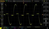
I checked triac but didn't find issues... here's what my trace looked like (I can't explain the high voltages, don't remember). Sorry, not much help.
This does match the image in the service manual for triac firing with no load.
1722772694656.png
RIGOL Print Screen3-16-2019 3_25_24 PM.256.jpeg
 
Last edited:
I discovered that based on the polarization of AC mains that either a full sine was seen or a half rectification from the steering diodes feeding the transmitter of the opto coupler. That cannot be correct.

Thinking if any one of those eight diodes in the triac triggering circuit are shorted or damaged could lead to a problem with correctly firing the triac. Ordered full set of FDH400 diodes.
 
Replaced the 8 FDH200 diodes in the triac triggering circuit.
Started looking at the amp with the AC mains line (hot)connected to thermal switch with AC mains neutral connected to fuse. In this configuration I believe you get the triac oscope image that I postef above.
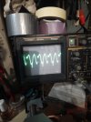
Changed mains polarization with AC mains line (hot) connected to fuse with AC mains neutral connected to thermal switch. In this configuration I get the triac oscope image as shown in the service manual.

Appears the triac is triggering properly but still have a 1-2 A current draw with RP200 set with lowest voltage on 55V rail.(35V)
Interesting is that the current draw reduces by almost 1A (drops to 0.8A draw) when the neutral is tied to earth ground?20240809_062900_copy_1500x2000.jpg
 
Last edited:
Was advised by friend to get off the mains AC circuit. Took the advice.
Had not tried injecting a signal.
Injecting a signal with speakers as load hum both channels.
Oscope showed what appears to be a .3V pulse on the RCA input grounds. Freq was measured at .7ms 149Hz. Will confirm this.
Pulling the high rail secondary wires does not eliminate the problem.
Since rectifiers of the 55V and 25V ps have been replaced..a knee jerk reaction ....replaced 12V rectifiers...still there.
Now chasing what most likely is the current drain.
Set up on dim bulb. Going to short triac and bring to approx 30VAC. Inject signal and probe circuitry to narrow down where this leakage is coming from.

Both channels affected. And yes lesson learned should have tried injecting a signal a long time ago.
 
Will someone who has a properly working M-200T measure the resistance of the mains within the amp?
Meaning with amp not connected to mains measure resistance between the two blades of the mains plug.
 
Last edited:
With power switch on it read 44k then slowly dropped to 18k. Then it jumped to 50k, dropped fast to 28k and continued that cycle. If I swap leads, I get different results.
 
This amp measures 545 ohms between mains. If leads are swapped same measurement. This is with the power switch closed.
When power switch is open it measures open.

Removed C84 from circuit no change. C84 measures open as it should.
 
Last edited:
Anyone else willing to measure the resistance between mains in a working M-200?

Used the Fluke85 to get the above measurement.
Measured with an Archer analog meter with 9V battery in the R10K position maximizing the current capability still measured 545 ohms.
 
Last edited:
S
With power switch on it read 44k then slowly dropped to 18k. Then it jumped to 50k, dropped fast to 28k and continued that cycle. If I swap leads, I get different results.
sol7 did you use a digital meter or analog? If digital mfger...model #?
 
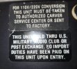
Interesting labels concerning sold at military club....must have left factory set up for 200V.
Do the T2 primary wire colors and locations look correct for 110V set up.
As well the jumper locations.
 

Attachments

  • 20241012_140558.jpg
    20241012_140558.jpg
    155.8 KB · Views: 11
  • 20241012_140911.jpg
    20241012_140911.jpg
    67.1 KB · Views: 11
Back
Top Bottom