


k6sti
Active Member

Rotate the mouse wheel to vary the termination resistance of a 10.7 MHz ceramic filter. Adjust for minimum group delay variation.
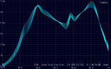
You can display an envelope of the changes.

You can separately adjust the input and output terminations. Each can include shunt capacitance.
No matching network is needed. Connect a 50 ohm VNA directly to the ceramic filter.
S-parameter plotter:
This shows what's possible for an isolated filter. But tuners use at least two of them. To properly characterize the pair, you need to measure them cascaded. I think the best way to optimize a tuner for minimum distortion is to use a VNA to select a batch of candidate filters based on filter amplitude response and group delay. Then measure tuner distortion while swapping selected filters (try reversing each). If you want even lower distortion, adjust the filter terminal impedances while installed.
The filter above looks like it's centered at 10.75 MHz so I set the frequency limits wider than usual. Only group delay within +/- 100 kHz of the IF center frequency matters. The amplitude response out to +/- 200 kHz matters for HD Radio sideband attenuation.
Brian
Last edited: