• The move to the new server is done. There are some software and database maintenance updates in process. This has us passing the hat around to help out. We appreciate any donations. Seriously, even a dollar helps. The payment page may be found here - https://www.audiokarma.org/support.html

Cerwin Vega VS-150 Crossover Recap

Bradley J

New Member
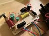
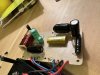
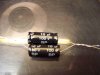
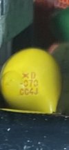
Just pulled the crossovers out of my Cerwin Vega VS-150 to recap and I noticed that all the caps are rated in MFD rather than the µF I’m used to. What would be the correct cap replacement value for the one pictured that reads 20 MFD 100V?

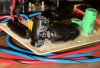
I am also curious if I only need to replace the 3 electrolytic caps seen on the board. I am not sure what the horizontal black things are as I can’t find the schematics or see labeling on them.
 

Attachments

  • 34730CF1-B2EA-4B79-9C90-1F675DBA61F7.jpeg
    34730CF1-B2EA-4B79-9C90-1F675DBA61F7.jpeg
    99.5 KB · Views: 93
  • 2EE2E896-7EDB-4721-A303-AF645BBB4394.jpeg
    2EE2E896-7EDB-4721-A303-AF645BBB4394.jpeg
    124.7 KB · Views: 93
  • E8F6942D-02EB-4243-A2AD-5264A622A3DB.jpeg
    E8F6942D-02EB-4243-A2AD-5264A622A3DB.jpeg
    121.5 KB · Views: 90
Register to hide this ad
MFD = MicroFarad = uF

To replace the 20MFD 100V you need a 20uF 100V (or higher voltage) capacitor. You need BP / NP or BI POLAR or NON POLARIZED electrolytic capacitors. If you use film capacitors, they are non polarized.

The black components are ferrite core inductors.
 
MFD = MicroFarad = uF

To replace the 20MFD 100V you need a 20uF 100V (or higher voltage) capacitor. You need BP / NP or BI POLAR or NON POLARIZED electrolytic capacitors. If you use film capacitors, they are non polarized.

The black components are ferrite core inductors.

Thanks for the clarification! Went down a rabbit hole where some sites said 1 mfd is 1000 uf, and some sites said what you just said. Good to know I’ll just be replacing these 3 caps too. Thanks!
 
MFD = MicroFarad = uF

To replace the 20MFD 100V you need a 20uF 100V (or higher voltage) capacitor. You need BP / NP or BI POLAR or NON POLARIZED electrolytic capacitors. If you use film capacitors, they are non polarized.

The black components are ferrite core inductors.
Also, I cannot seem to find BP/NP 20uf caps on the market besides those large Daytona caps. The caps do say +\-10%. Does that mean I can do plus or minus 10% of the capacitance, ie getting a 22uf cap instead?
 
Also, I cannot seem to find BP/NP 20uf caps on the market besides those large Daytona caps. The caps do say +\-10%. Does that mean I can do plus or minus 10% of the capacitance, ie getting a 22uf cap instead?

I have 9 brand new of these so I thought I would
test them with my LCR meter to check how close
they matched. here are the readings.
21.2 , 21.3 , 21.3 , 21.5 , 22.5 , 22.6 , 22.6 , 22.7 , 22.8

22uF 100V Electrolytic Non-Polarized Crossover Capacitor (parts-express.com)
 
Even if I bet those capacitors are still fine, you could use two 10uF in parallel, or one 22uF , a bit on the high side but probably ok for that application.
 
Even if I bet those capacitors are still fine, you could use two 10uF in parallel, or one 22uF , a bit on the high side but probably ok for that application.
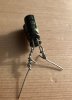
What would be the process of combining two capacitors and what would that look like? For the 90uf cap on the board, I’m planning on combining two 47uf caps. I’m just not sure how I would go about using them in parallel and what that looks like physically.
 
What would be the process of combining two capacitors and what would that look like? For the 90uf cap on the board, I’m planning on combining two 47uf caps. I’m just not sure how I would go about using them in parallel and what that looks like physically.

Like this. solder the legs together.

100_8114.JPG
 
Like this. solder the legs together.

View attachment 2775713
Sweet, thanks for the clarification. I was messing around yesterday and did this with some extra caps I had. Very very sloppy but I was just getting the idea of what I’ll need to do. I’ll be sure to cut the legs down more and not twist tie them like shown haha.
 

Attachments

  • 1C9EA1EE-275C-4F9B-9CD7-A9745AD7E990.jpeg
    1C9EA1EE-275C-4F9B-9CD7-A9745AD7E990.jpeg
    84.4 KB · Views: 12
I owned a pair of VS-150's many years ago, they did seriously rock using A Sansui AU-7700 for power......:thumbsup:
 
I've been using VS-120s for a number of years. I redid the crossovers four years ago and refoamed the woofers.

Can't really say that I noticed any difference between the old caps and the new ones. They are really awesome speakers, though.

I assume that the 15" woofers bring a little more thunder than the 12s! Haha
 
I was wondering if anyone here knows what size of PTC is used in the VS-150 Crossover? This is the best picture I could get of it.
 

Attachments

  • IMG_0761.jpeg
    IMG_0761.jpeg
    28.9 KB · Views: 7
Back
Top Bottom