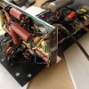
I have a 50's amp with the preamp section separate. I have a ground issue since if I jumper the two pieces the noise goes down. I'm checking ground connections. This amp uses chassis ground as the tube sockets ground to the chassis but then it also has a small wire running through the amp from one ground tie of each socket and travels through the amp. Build quality is high so I assume this method worked well enough when new.
Three Questions:
1.) The bus wire in the preamp section of the three 6sn7 tubes and input jack does not connect to the buss wire of the tone control and power supply filter section of that one piece preamp. In fact the very first 6sn7 preamp tube doesn't have it's tube socket grounded to the ones right next to it. Was this a mistake in production and I should connect everything to the single bus wire?
2.) Does the lower impedance of the bus wire compared to the chassis cause the ground to travel through the bus wire rather than through the chassis and therefore not create a ground loop? I ask this since if each socket or jack is connected to the chassis and has a ground bus wire, isn't that a possible ground loop?
3.) If I am correct about the impedance of the wire, and the wire is somewhat small, would I decrease impedance in the ground bus by using a larger copper wire?
I'm not planning on completely changing the ground system of this amp as I'm sure they knew what they were doing when it was built, I'm just looking to help it out and correct the possible mistake.
Three Questions:
1.) The bus wire in the preamp section of the three 6sn7 tubes and input jack does not connect to the buss wire of the tone control and power supply filter section of that one piece preamp. In fact the very first 6sn7 preamp tube doesn't have it's tube socket grounded to the ones right next to it. Was this a mistake in production and I should connect everything to the single bus wire?
2.) Does the lower impedance of the bus wire compared to the chassis cause the ground to travel through the bus wire rather than through the chassis and therefore not create a ground loop? I ask this since if each socket or jack is connected to the chassis and has a ground bus wire, isn't that a possible ground loop?
3.) If I am correct about the impedance of the wire, and the wire is somewhat small, would I decrease impedance in the ground bus by using a larger copper wire?
I'm not planning on completely changing the ground system of this amp as I'm sure they knew what they were doing when it was built, I'm just looking to help it out and correct the possible mistake.