• The move to the new server is done. There are some software and database maintenance updates in process. This has us passing the hat around to help out. We appreciate any donations. Seriously, even a dollar helps. The payment page may be found here - https://www.audiokarma.org/support.html

Chinese FU19 (5894) amplifier questions

Pyro15D

New Member
Hey everyone. I've been a lurker for years but decided to take the plunge and post a question to see your thoughts on the design of this interesting amplifier.

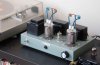
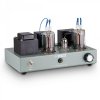
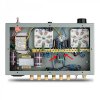
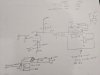
It is a stereo tube amplifier using half of one 6n2 to drive both portions of the FU-19 tetrode in single-ended mode. I pulled the bottom cover off (see attached pictures) to draw out a schematic of the circuit. For simplicity purposes, I only drew one channel. I also left out the "headhone circuitry." It is just a DPDT switch on the 8ohm tap that switches the output to the 8ohm speaker output post or to the headhone jack via a 150ohm resistor. I have a couple questions:

1) Why are the plates of the FU19 connected to the output transformer via 20ohm resistors? Why wouldn't they just be connected directly?

2) Why is there a feedback loop from the 8ohm tap from the output transformer to the cathode bias circuit for the 6n2?

As far as sounds, the amplifier sounds really quite nice albeit a bit thin. I imagine my speakers (KEF K120) probably aren't doing the amplifier too many favors. Aside from that, really quite nice with no hum or weird behavior. Power transformer gets toasty but I can still hold my hand on it, so probably nothing to worry about. I have a pair of 5894A tubes on the way to me to get rid of the average at best Chinese tubes currently installed as well as a 12AX7 to replace the 6n2. Anyway, below are the pictures. If you have any more questions, let me know.
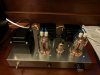
Amp Schematic.jpg Amp outside.jpg Amp inside.jpg
 
Register to hide this ad
1) probably to allow for imperfect section to section matching. If they were connected directly, usually what you find is that one section does more work than the other. A voltage measurement across those resistors will show how well matched they actually are at idle at least. Under dynamic conditions might be a different story.

2) it flattens out the frequency response and reduces distortion. It also reduces the output impedance of the amp so its less sensitive to speaker selection.


can you confirm the value of the grid to ground resistor at the FU19? Almost looks like 25k. If its that low, a 0.22uf coupling cap doesn't make a lot of sense. It puts a -3db point of about 29 hz, but you'd have a fair bit of phase shift before that point. If the grid resistor is that low, I'd figure something more like a 1.0uf cap, provided it doesn't cause low frequency instability or just saturate the transformers. Might even be able to go larger.
 
Thanks for the reply. I apologize about my chicken scratch writing. The grid to ground is 225K, not 25K. Also the coupling cap is .27uf.

For #1, good idea with the meter for voltage drop across the plate resistors. I'll see how matched they are. I would like to reduce that value (or bypass them completely) if possible. I know these Chinese amps wouldn't put additional components in there for no reason, so I figured they were put in there for something. I wonder how much potential power goes wasted through those resistors though.

For #2 and in general, what are good books to read for tube amplifier design? I never would have thought of that as a way to affect output impedance.
 
1) This is common practice in SS amps with parallel devices. Doesn't seem to be as common with parallel tube circuits, probably because tubes are voltage devices, and not current devices. So in essence, they are putting a resistance in series with a conductance. I'm not sure I am explaining it, or even thinking of it correctly. The point is that while clearly needed in BJT's and MOSFET's, I'm not as convinced it is necessary in tubes. Probably the designer just thought it was "best practice". The same for the (2) 100 ohm resistors on the grid. I fully realize that the designer, by definition, is a professional designer, and I am not, but I am still going to say it -- Transistor mentality.

2) This is very typical "global" feedback. It is seen in most tube amp designs discussed on these forums.

I read 225K for the grid to ground resistor. I think that would alliviate @gadget73 's concern.

I also thought you wrote 760V for the plate voltage! Then I saw 260V at the PS. 760V would definately justify top caps, but 260V really does not. I get that they are using those tubes for visual effect, and it does look cool.
 
Its probably not losing all that much through those 20R resistors. I'd be surprised if you get more than a half watt by eliminating them entirely.

and yeah, 225k (not a standard value) with an 0.27uf cap is fine.

Tons of books about amp design, Morgan Jones' Valve Amplifiers is often mentioned. I haven't read it, but I should. The Radiotron Designer's Handbook can be found online but its a *really* dry read and isn't limited to just audio amp design.
 
That 20 Ohm resistor is called a "Parasitic Suppressor"

That's an RF amplifier tube. The resistors "de-Q" the high frequency resonant circuit formed by the two plate connections - remove them and you will likely have an VHF oscillator. It's good practice to put resistors in the plate leads when tubes or sections of tubes are paralleled for this reason. 47 or 50 Ohms is most commonly used, but maybe 20 Ohms was found to be enough...

Resistors here are also helpful for checking section matching - the cathode is common, so you can't check it there. If half gets weak, the other half will carry all the current and cook.
 
I was going to post a comment along the lines of: "Tubes that look like that should be connected to a SO-239, not an audio transformer", but I refrained.

... Well, until now, I guess.:rolleyes::)

Other than that, Thanks @Tom Bavis for the education.
 
Thanks everyone for the education. I figured the Chinese people making this would have a reason for putting in what I initially thought were "extra" components. In response to gadget73 earlier, after leaving the amplifier on for 2 hours, I checked the voltage across each plate capacitor and the values are as follows: Left channel: .623 and .522; Right channel: .616 and .523 volts. The voltage at the plates is 234 volts as well so I guess 26 volts is going through the output transformer. So, with ohm's law each section is running at right around 31ma at idle, which is less than half of what is listed for zero signal current in the datasheet for the 5894 tube (which this is the Chinese copy of). Tube is probably on fairly light duty I would imagine then. I can't really do a whole lot more detailed measurements since I am here in a hotel room for the next couple weeks so I'm limited to what a DMM will reveal. I will say, I keep waiting for the amp to up and go POP, but it has been really well behaved so far. Not bad for a $150 amp.
 
Hello everyone, my first post in this group, can't express how grateful I am for the education I got here. I also got lured by the warm glow of a cheap Chinese FU19 amplifier. What I'm finding really attractive (other than price tag of ~200 euro door to door) is its simplicity. The amp has arrived after a full month of travel. Packaging prooved sufficient, however I've seen a few better wrapped things in my life. There's no diagram, manual, leaflet, anything, except a piece of torn away paper in Chinese. Happily, the thing is pretty straightforward to setup. Qualitywise, it's a nice piece of electrical engineering, with just one visible fault. The plate connections - two blue wires you connect to the top of each power tube - are the ugliest pieces of thin wires in single PVC insulation I've seen in my life. Considering the plate voltage is 260 V DC, which can easily kill, this is clearly a serious shock hazard. Replacing these with a properly insulated connectors will be the first thing I will do. Now, the most important - the amp plays very, very well. And I have and had over time quite a few amps, so I think I know what I'm talking about.
 
Hello everyone, my first post in this group, can't express how grateful I am for the education I got here. I also got lured by the warm glow of a cheap Chinese FU19 amplifier. What I'm finding really attractive (other than price tag of ~200 euro door to door) is its simplicity. The amp has arrived after a full month of travel. Packaging prooved sufficient, however I've seen a few better wrapped things in my life. There's no diagram, manual, leaflet, anything, except a piece of torn away paper in Chinese. Happily, the thing is pretty straightforward to setup. Qualitywise, it's a nice piece of electrical engineering, with just one visible fault. The plate connections - two blue wires you connect to the top of each power tube - are the ugliest pieces of thin wires in single PVC insulation I've seen in my life. Considering the plate voltage is 260 V DC, which can easily kill, this is clearly a serious shock hazard. Replacing these with a properly insulated connectors will be the first thing I will do. Now, the most important - the amp plays very, very well. And I have and had over time quite a few amps, so I think I know what I'm talking about.
What kit did you build? And is it quiet?
I've thought about building one with those tubes,or anothers like them.
 
It wasn't a kit, it arrived ready built. Looks exactly like a visually refreshed model mentioned by Pyro15D at the beginning of this thread. Pls see attached picture. I've already replaced the anode connections for a proper 500V rated wire. looks a bit strange now, but at least I'm not afraid someone will get shocked touching the thing.
IMG_7562.jpg
That's how it originally looked:
$_10.jpg
And yes, it is dead, velvet quiet, even when I put my ear straight to the speaker.
(Edit) Removing global feedback improves sound considerably. The wires marked with red arrows.
 

Attachments

  • Global-feedback.jpg
    Global-feedback.jpg
    147.2 KB · Views: 246
Last edited:
Hey everyone. I've been a lurker for years but decided to take the plunge and post a question to see your thoughts on the design of this interesting amplifier.

It is a stereo tube amplifier using half of one 6n2 to drive both portions of the FU-19 tetrode in single-ended mode. I pulled the bottom cover off (see attached pictures) to draw out a schematic of the circuit. For simplicity purposes, I only drew one channel. I also left out the "headhone circuitry." It is just a DPDT switch on the 8ohm tap that switches the output to the 8ohm speaker output post or to the headhone jack via a 150ohm resistor. I have a couple questions:

1) Why are the plates of the FU19 connected to the output transformer via 20ohm resistors? Why wouldn't they just be connected directly?

2) Why is there a feedback loop from the 8ohm tap from the output transformer to the cathode bias circuit for the 6n2?

As far as sounds, the amplifier sounds really quite nice albeit a bit thin. I imagine my speakers (KEF K120) probably aren't doing the amplifier too many favors. Aside from that, really quite nice with no hum or weird behavior. Power transformer gets toasty but I can still hold my hand on it, so probably nothing to worry about. I have a pair of 5894A tubes on the way to me to get rid of the average at best Chinese tubes currently installed as well as a 12AX7 to replace the 6n2. Anyway, below are the pictures. If you have any more questions, let me know.
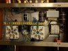
View attachment 1658189 View attachment 1658190 View attachment 1658191
You know the so let will have to be rewired for the 12ax7, right? I have q phono preamp that has switches connected to the sockets to be able.to use 6N2's or 12ax7's. What's the output of the amp?
 
The output, as per manufacturer, is about 2x4W. That's not too much but with my speakers it fills my 6 x7 m room sufficiently, while the pot shows 12 hours. I hope I'm not under self-inducted illusion, but it seems that after feedback cut-off, it plays not only clearer and more precise, but also louder.
I think I will consider replacing the 6n2 for a 12xa7 after a while, when my fingers will start itching again to change something, For now, I just enjoy :)
 
Last edited:
4 watts is enough. A SEUL amp I have puts out 5.5wpc and drives my speakers pretty good. You could always just use a socket adaptor to go from 6n2 to 12ax7.
 
Hi folks!

I, too, have one of these FU19 / 5894A based amplifiers. I’m new to (tube) electronics and have a question I’m hoping someone can answer for me – and maybe explain how they came-up with the answer.

In looking at the schematic Pyro15D drew and posted (that you much for that!), I’m trying to figure out what the primary / input impedance is for the output transformers.

EDIT - according to the data sheet for the 5894 tube, the plate-to-plate resistance is 4.4k-8k. Would this suggest that a OPT with a primary impedance of 10k would be an acceptable match?

I've attached the data sheet for reference.

Thank you much for any help.
 

Attachments

Last edited:
View attachment 1858201
And yes, it is dead, velvet quiet, even when I put my ear straight to the speaker.
(Edit) Removing global feedback improves sound considerably. The wires marked with red arrows.
I tried cutting the global feedback wires, and in my system (Altec VOTT A7-500), it added extra harmonic bloom from top to bottom. It became more "tubey," forgiving, and warm but for my system, I preferred the feedback in place, which sounded cleaner with better imaging and bass punch. YMMV.
 
Back
Top Bottom